TEA1206 Просмотр технического описания (PDF) - Philips Electronics
Номер в каталоге
Компоненты Описание
Список матч
TEA1206 Datasheet PDF : 16 Pages
| |||
Philips Semiconductors
High efficiency DC/DC converter
Preliminary specification
TEA1206T
SYMBOL
PARAMETER
CONDITIONS
MIN. TYP. MAX. UNIT
Temperature
Tamb
Tmax
operating ambient temperature
internal cut-off temperature
−40
+25
+80
°C
150
175
200
°C
Digital levels
VlL
LOW-level input voltage pins 1, 5 and 8
VIH
HIGH-level input voltage pin 1
note 6
VIH
HIGH-level input voltage pins 5 and 8 note 6
0
−
V3 − 0.4 −
0.55V3 −
0.5
V
V3 + 0.3 V
V3 + 0.3 V
Notes
1. At Vi lower than the target output voltage, but higher than 2.8 V, the PFET will remain conducting (100% duty cycle),
resulting in Vo following the input voltage.
2. The undervoltage lockout level shows wide specification limits since it decreases at increasing temperature. Since
the minimum supply voltage of the digital control part also decreases when temperature goes up, correct operation
of this function is guaranteed over the whole temperature range.
3. V3 is the voltage at pin 3 (UPOUT/DNIN).
4. Current limit is defined by an external resistor Rlim, having 1% accuracy. The typical value is presettable between
0.5 and 5.0 A with a spread of ±17.5%.
5. The specified efficiency is valid when using an output capacitor having an ESR of 0.10 Ω and a Coilcraft
DT1608C-103 10 µH small size inductor.
6. If the applied high level is less than V3 − 1 V, the quiescent current level of the device will increase.
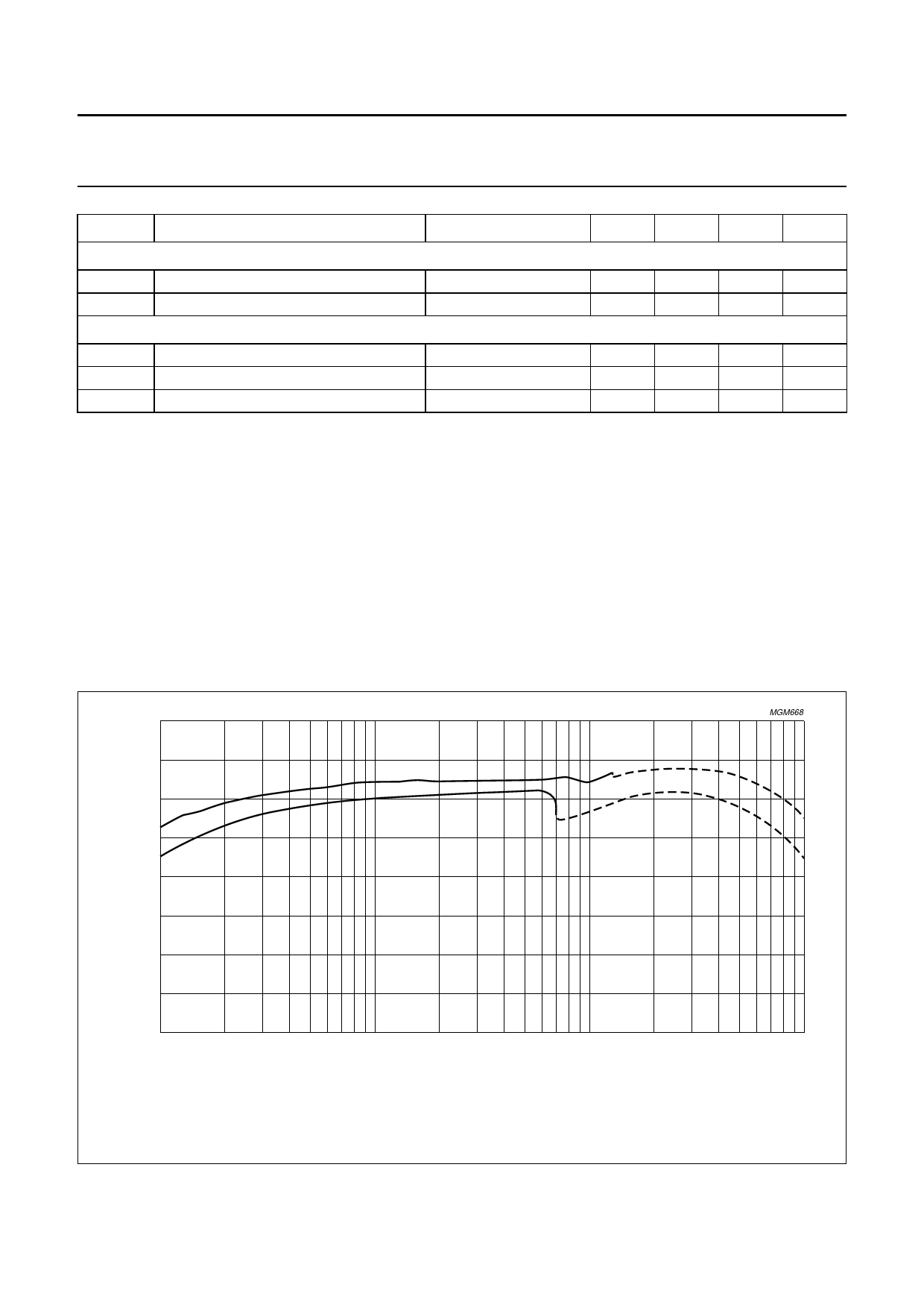
100
handbook, full pagewidth
efficiency
(%)
(1)
90
(2)
MGM668
80
70
60
1
10
102
IL (mA)
103
(1) Represents the curve for upconversion from 3.6 to 4.6 V. The solid line indicates PFM and the dashed line indicates PWM.
(2) Represents the curve for downconversion from 3.6 to 1,8 V. The solid line indicates PFM and the dashed line indicates PWM.
Vi = 3.6 V; L = 10 µH (DT1608-103); Cout = 330 µF (Sprague 595D) capacitor.
Fig.5 Efficiency as a function of load current IL.
1999 Sep 16
10
Share Link: 