W83194R-37 Просмотр технического описания (PDF) - Winbond
Номер в каталоге
Компоненты Описание
Список матч
W83194R-37 Datasheet PDF : 19 Pages
| |||
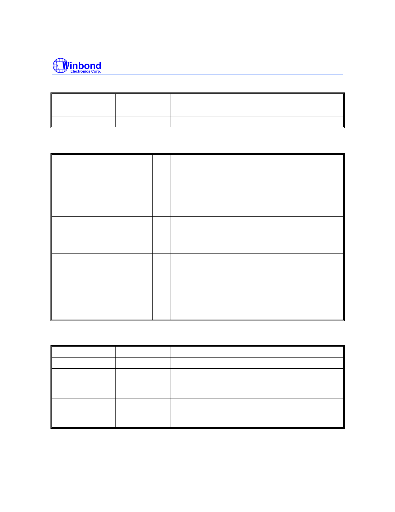
Preliminary W83194R-37/-58
5.3 I2C Control Interface
SYMBOL
PIN
SDATA
23
SDCLK
24
I/O
FUNCTION
I/O Serial data of I2C 2-wire control interface
IN Serial clock of I2C 2-wire control interface
5.4 Fixed Frequency Outputs
SYMBOL
PIN
REF0/ CPU3.3#_2.5
2
REF1/*SD_SEL#
46
24MHz/ *MODE
25
48MHz/ *FS0
26
I/O
FUNCTION
I/O Internal 250 KΩ pull-up.
Latched input for CPU3.3#_2.5 at initial power up.
Reference clock during normal operation.
Latched high - VDDq2b = 2.5V
Latched low - VDDq2b = 3.3V
I/O Internal 250 KΩ pull-up.
Latched input at Power On selects either CPU(SDSEL = 1)
or AGP(SD_SEL = 0) frequencies for SDRAM clock
outputs.
I/O Internal 250 KΩ pull-up.
Latched input for MODE at initial power up. 24 MHz output
for super I/O during normal operation.
I/O Internal 250 KΩ pull-up.
Latched input for FS0 at initial power up for H/W selecting
the output frequency of CPU, SDRAM and PCI clocks. 48
MHz output for USB during normal operation.
5.5 Power Pins
SYMBOL
VDD
VDDq2
VDDq2b
VDDq3
Vss
PIN
FUNCTION
1
Power supply for Ref [0:1] crystal and core logic.
42
Power supply for AGP1 and REF1 output, either 2.5V or
3.3V.
48
Power supply for CPUCLK[0:3], either 2.5V or 3.3V.
6, 14, 19, 30, 36 Power supply for SDRAM, PCICLK and 48/24 MHz outputs.
3, 9, 16, 22, 27, Circuit Ground.
33, 39, 45
-4-
Share Link: 