PBL3853 Просмотр технического описания (PDF) - Ericsson
Номер в каталоге
Компоненты Описание
Список матч
PBL3853 Datasheet PDF : 16 Pages
| |||
PBL 3853
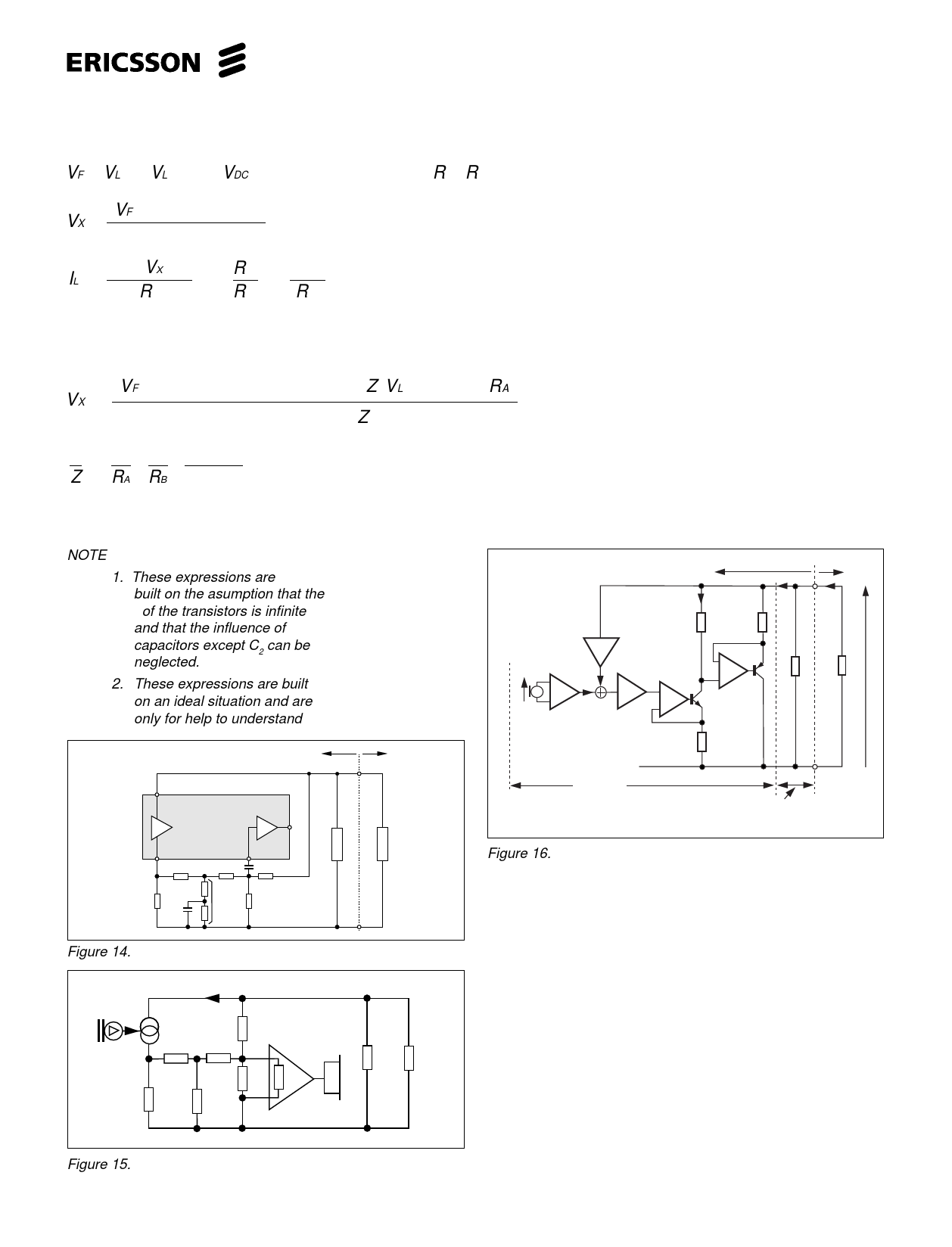
Expression for DC-characteristics. from figure16, (empirical).
( ) VF = VL − (VL − 1.3 − VDC) 0.07 ⋅10−3 + 0.6 ⋅10−3 (R1 + R2) ....................................................................................8
VX = (VF − 2.0) / 45 + 0.14 .......................................................................................................................................9
0.18
IL =
5.8 (VX − 1)
R5
1+
R12
R13
+
0.65 ...........................................................................................................................10
R13
If the resistors RA and RB are connected in the circuit as in figure 16, the VX
will have somewhat more complex expression:
( ( ) ) VX =
(VF − 2.0) / 45⋅103 + 0.14 ⋅10−3 + (Z VL ) / 2.5 ⋅103RA
0.18 ⋅10−3 + 1/ 2.5 ⋅103 − Z 2.5 ⋅103 2
................................................................................11
1
Z
=
1
RA
+
1
RB
+
0. 65
2.5 ⋅103
If the resistors RA and RB are set to infinity in this expression it will take the same form as above.
NOTE
1. These expressions are
built on the asumption that the
βof the transistors is infinite
and that the influence of
capacitors except C2 can be
neglected.
2. These expressions are built
on an ideal situation and are
only for help to understand
Telephone
set side
a
PBL 3853
Tx
Rx 16
Z2
2
15
b
R6 C R7
R11
R8
R5
Zbal
R10
C6
R9
Line side
Z1
Figure 14.
IL
V+L
VTO
R6
R11
R7
R10 RI Zin
R5
Zbal
R19 ZLine
Figure 15.
Telephone
ILoad
Line
IL
I1
R12
R13
γ
-
V
δ
+
α
+
-
V
R5
Zp
ZLine
VL
Active impedance
section
Passive impedance
section
Figure 16.
MUTE and Cut-off Function
The receiver mute (pin 17) is a cut-off function. The normal
receiver amplifier is cut-off but a second amplifier is activated
to let the DTMF or the payphone signal injected to pin 17 get
through to the earphone. The input level for cut-off:
V cut-off = Rx output (VDC/2) + 2x V diode ≈ 2.2 V + 1.3 V ≈
3.5 V
The signal for DTMF confidence tone in the earphone must
be injected to pin 17 at correct DC level or via a capacitor.
The mute signal is taken from pin 18 via a resistor in series
with at diode. The diode is needed in order not to disturb the
DC-level at pin 17 in not muted condition.
The transmit mute (pin 10) can be taken from the same point
(pin 18) with a series resistor (see figure 10).
9
Share Link: 