NLX2G66MU3TCG(2016) Просмотр технического описания (PDF) - ON Semiconductor
Номер в каталоге
Компоненты Описание
Список матч
NLX2G66MU3TCG Datasheet PDF : 11 Pages
| |||
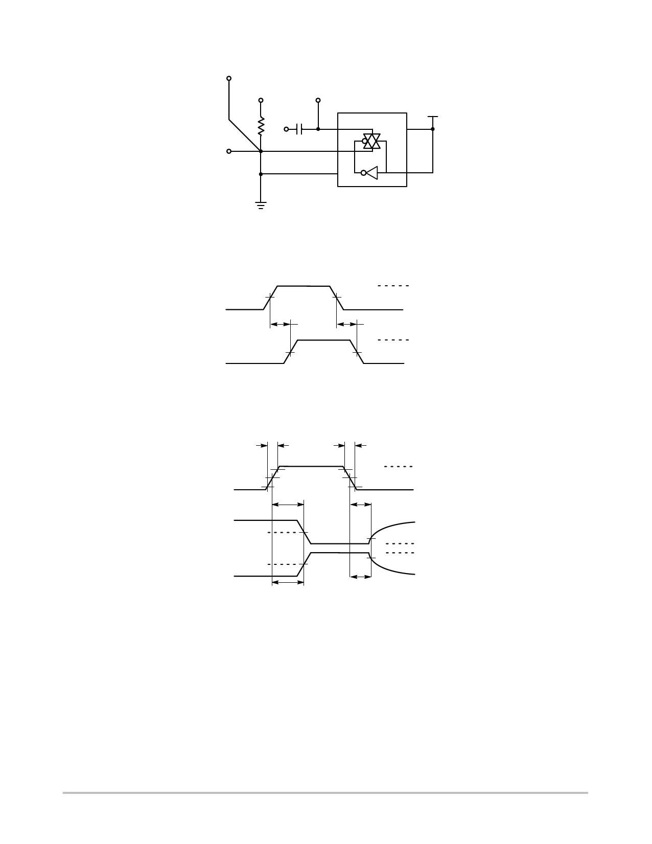
NLX2G66
To Distortion
Meter
(VCC)/2
VIS
RL
VOS
0.1 mF
fin
VCC
VCC
GND
*Includes all probe and jig capacitance.
Figure 12. Total Harmonic Distortion Test
Set−Up
XA
50%
VCC
50% VCC
tPLH
YA
50% VCC
tPHL
VOH
VOL
Figure 13. Propagation Delay, Analog In to
Analog Out Waveforms
tr
tf
Control 90%
10%
tPZL
50% VCC
Analog Out
50% VCC
tPZH
VCC
50% VCC
tPLZ
High
Impedance
10%
VOL
90%
VOH
High
tPHZ Impedance
Figure 14. Propagation Delay, ON/OFF Control
www.onsemi.com
8
Share Link: 