MT3S05T Просмотр технического описания (PDF) - Toshiba
Номер в каталоге
Компоненты Описание
Список матч
MT3S05T Datasheet PDF : 3 Pages
| |||
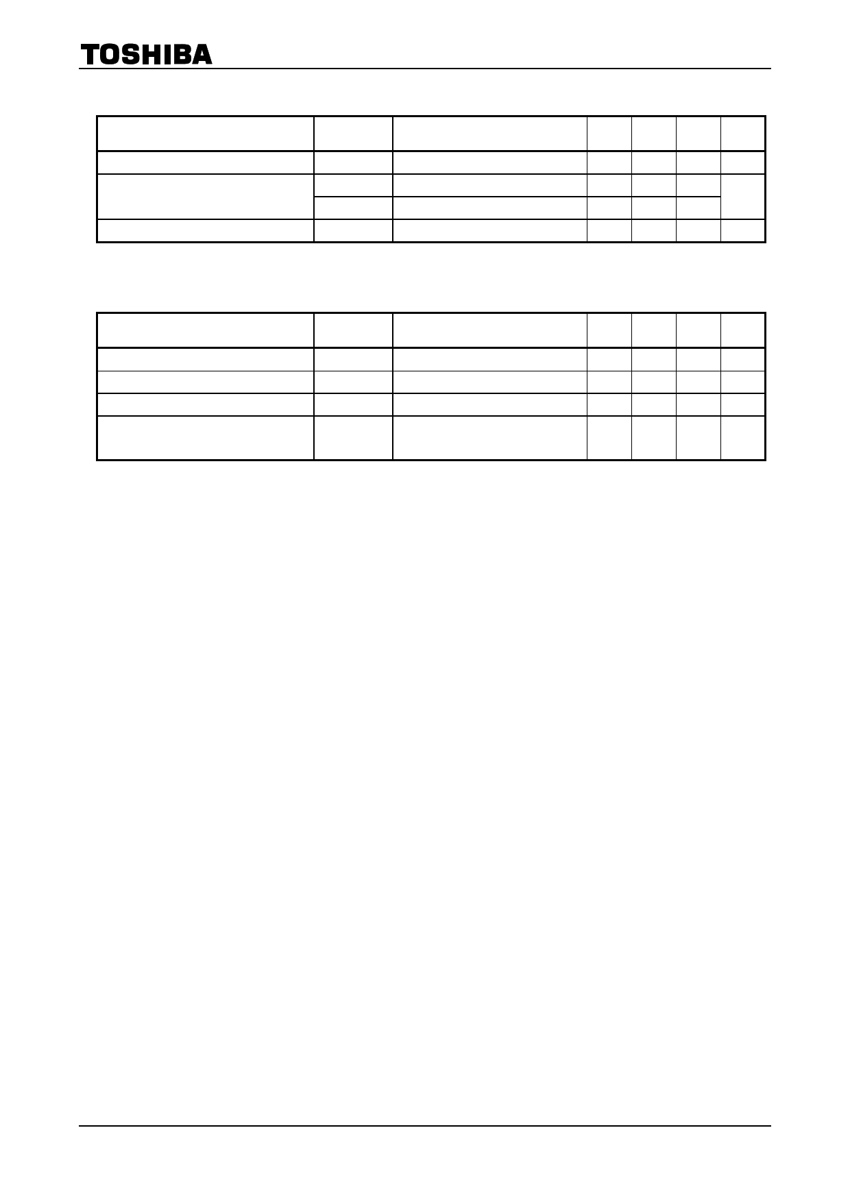
Microwave Characteristics (Ta = 25°C)
Characteristics
Transition frequency
Insertion gain
Noise figure
Symbol
Test Condition
fT
|S21e|2(1)
|S21e|2(2)
NF
VCE = 1 V, IC = 5 mA
VCE = 1 V, IC = 5 mA, f = 1 GHz
VCE = 3 V, IC = 20 mA, f = 1 GHz
VCE = 1 V, IC = 5 mA, f = 1 GHz
MT3S05T
Min Typ. Max Unit
2
4.5
⎯ GHz
⎯
8.5
⎯
dB
8.5 11.5 ⎯
⎯
1.4
2.2
dB
Electrical Characteristics (Ta = 25°C)
Characteristics
Symbol
Test Condition
Min Typ. Max Unit
Collector cut-off current
Emitter cut-off current
DC current gain
Reverse transfer capacitance
ICBO
IEBO
hFE
Cre
VCB = 5 V, IE = 0
⎯
VEB = 1 V, IC = 0
⎯
VCE = 1 V, IC = 5 mA
80
VCB = 1 V, IE = 0, f = 1 MHz
⎯
(Note)
⎯
0.1
μA
⎯
1
μA
⎯
140
⎯
0.9 1.25 pF
Note: Cre is measured by 3 terminal method with capacitance bridge.
Caution
This device is sensitive to electrostatic discharge. Please handle with caution.
2
2007-11-01
Share Link: 