MAX9737 Просмотр технического описания (PDF) - Maxim Integrated
Номер в каталоге
Компоненты Описание
Список матч
MAX9737 Datasheet PDF : 13 Pages
| |||
Mono 7W Class D Amplifier
Mute Function
The MAX9737 features a mute mode where the signal is
attenuated at the speaker and the outputs stop switch-
ing. To mute the MAX9737, drive MUTE low.
Click-and-Pop Suppression
The MAX9737 features comprehensive click-and-pop
suppression and precharge circuitry that reduce audi-
ble transients on startup and shutdown. The precharge
circuit enables the amplifier within 10ms without any
clicks or pops. Connect PC between the input resistor
(RIN) and the input capacitor (CIN). For optimal click-
and-pop suppression, use a 0.47µF input coupling
capacitor (CIN).
Current Limit
When output current exceeds the current limit, 4.6A
(typ), the MAX9737 disables the outputs and initiates a
450µs startup sequence. The shutdown and startup
sequence is repeated until the output fault is removed.
Properly designed applications do not enter current-
limit mode unless the output is short circuited or con-
nected incorrectly.
Thermal Shutdown
When the die temperature exceeds the thermal-shut-
down threshold, +160°C (typ), the MAX9737 outputs
are disabled. When the die temperature decreases by
30°C, normal operation resumes. Some causes of ther-
mal shutdown are excessively low load impedance,
poor thermal contact between the MAX9737’s exposed
pad and the PCB, elevated ambient temperature, or
poor PCB layout and assembly.
Applications Information
Filterless Class D Operation
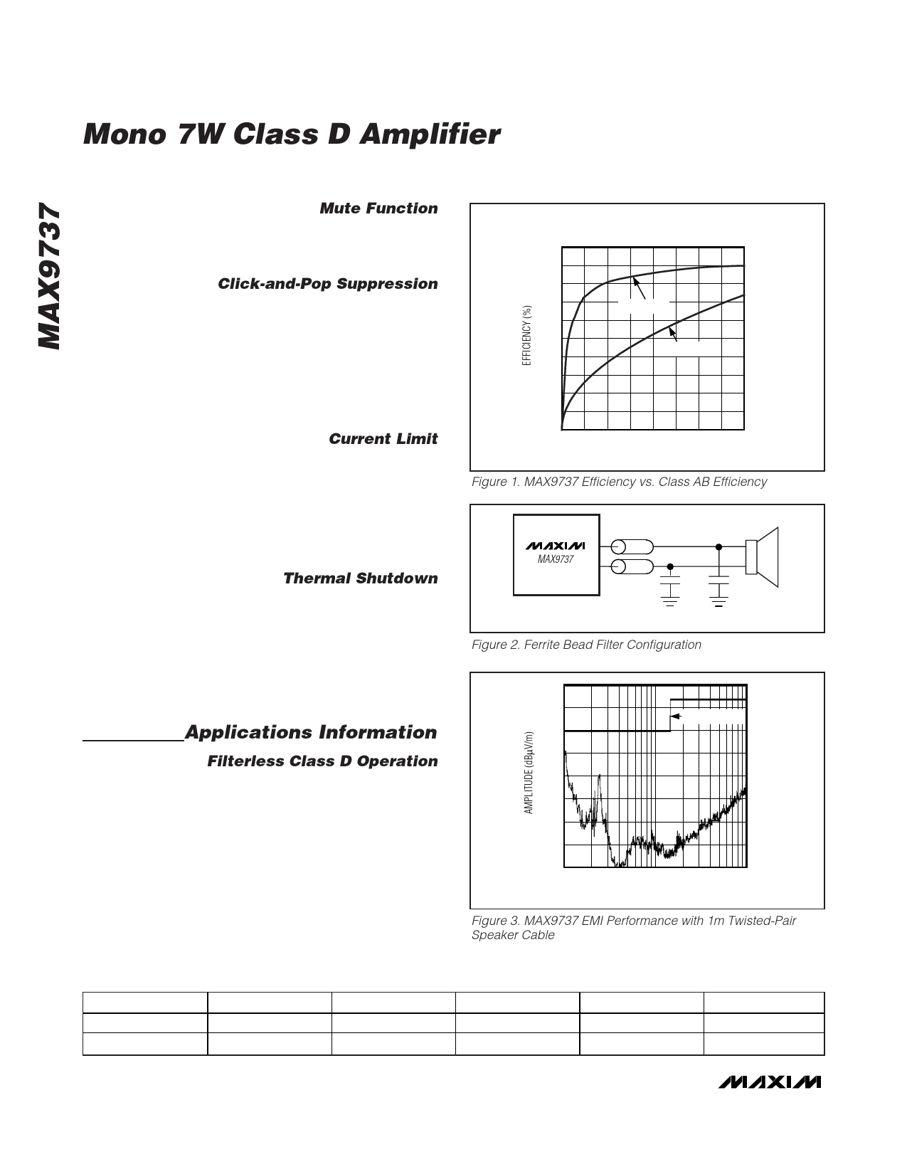
The MAX9737 meets EN55022B EMC radiation limits
with an inexpensive ferrite bead and capacitor filter
when the speaker leads are less than or equal to 1m
(Figure 3). Select a ferrite bead with 100Ω to 600Ω
impedance, and rated for 2A. The capacitor value
varies based on the ferrite bead chosen and the speak-
er lead length. See Figure 2 for the correct connections
of these components.
Table 1. Suggested Values for LC Filter
RL (Ω)
4
8
L1, L2 (µH)
10
15
C1 (µF)
0.47
0.15
EFFICIENCY
vs. OUTPUT POWER
100
90
80
70
MAX9737
60
50
CLASS AB
40
30
20
10
0
012345678
OUTPUT POWER (W)
Figure 1. MAX9737 Efficiency vs. Class AB Efficiency
MAX9737
FB1
FB2
C1
C2
330pF
330pF
FB1 AND FB2: WURTH742792040
Figure 2. Ferrite Bead Filter Configuration
40
35
30
25
20
15
10
5
0
30
EN55022B LIMIT
100
1000
FREQUENCY (MHz)
Figure 3. MAX9737 EMI Performance with 1m Twisted-Pair
Speaker Cable
C2, C3 (µF)
0.10
0.15
C4, C5 (µF)
0.22
0.15
R1, R2 (Ω)
10
15
8 _______________________________________________________________________________________
Share Link: 