ISL97645(2006) Просмотр технического описания (PDF) - Intersil
Номер в каталоге
Компоненты Описание
Список матч
ISL97645 Datasheet PDF : 14 Pages
| |||
ISL97645
Absolute Maximum Ratings
Lx to GND, AGND and PGND . . . . . . . . . . . . . . . . . . . . -0.5 to +25V
VDD2, OUT, NEG and POS
to GND, AGND and PGND. . . . . . . . . . . . . . . . . . . . . -0.5 to +25V
VDD1, VGH and VGH_M
to GND, AGND and PGND. . . . . . . . . . . . . . . . . . . . . -0.5 to +32V
Differential Voltage Between POS and NEG . . . . . . . . . . . . . . . ±6V
Voltage Between GND, AGND and PGND . . . . . . . . . . . . . . . ±0.5V
All Other Pins to GND, AGND and PGND . . . . . . . . . . -0.5 to +6.5V
Input, Output, or I/O Voltage . . . . . . . . . . . GND -0.3V to VIN + 0.3V
Recommended Operating Conditions
Input Voltage Range, VS . . . . . . . . . . . . . . . . . . . . . . . . 2.7V to 5.5V
Boost Output Voltage Range, AVDD . . . . . . . . . . . . . . . . . 8V to 20V
Input Capacitance, CIN . . . . . . . . . . . . . . . . . . . . . . . . . . . . . . .22µF
Boost Inductor, L1 . . . . . . . . . . . . . . . . . . . . . . . . . . . 3.3µH to 10µH
Output Capacitance, COUT . . . . . . . . . . . . . . . . . . . . . . . . . . 2x22µF
Operating Ambient Temperature Range . . . . . . . . . .-40°C to +85°C
Operating Junction Temperature . . . . . . . . . . . . . . .-40°C to +125°C
Thermal Information
Thermal Resistance
θJA (°C/W) θJC (°C/W)
4x4 QFN Package (Notes 1, 2) . . . . . .
39
2.5
Storage Temperature . . . . . . . . . . . . . . . . . . . . . . . .-65°C to +150°C
Power Dissipation . . . . . . . . . . . . . . . . . . . . . . . . . . . . . See Curves
Maximum Continuous Junction Temperature . . . . . . . . . . . . 125°C
Power Dissipation
TA ≤ 25°C . . . . . . . . . . . . . . . . . . . . . . . . . . . . . . . . . . . . . . .2.44W
TA = 70°C . . . . . . . . . . . . . . . . . . . . . . . . . . . . . . . . . . . . . . .1.34W
TA = 85°C . . . . . . . . . . . . . . . . . . . . . . . . . . . . . . . . . . . . . . .0.98W
TA = 100°C . . . . . . . . . . . . . . . . . . . . . . . . . . . . . . . . . . . . . .0.61W
CAUTION: Stresses above those listed in “Absolute Maximum Ratings” may cause permanent damage to the device. This is a stress only rating and operation of the
device at these or any other conditions above those indicated in the operational sections of this specification is not implied.
NOTES:
1. θJA is measured in free air with the component mounted on a high effective thermal conductivity test board with “direct attach” features. See Tech
Brief TB379.
2. For θJC, the “case temp” location is the center of the exposed metal pad on the package underside.
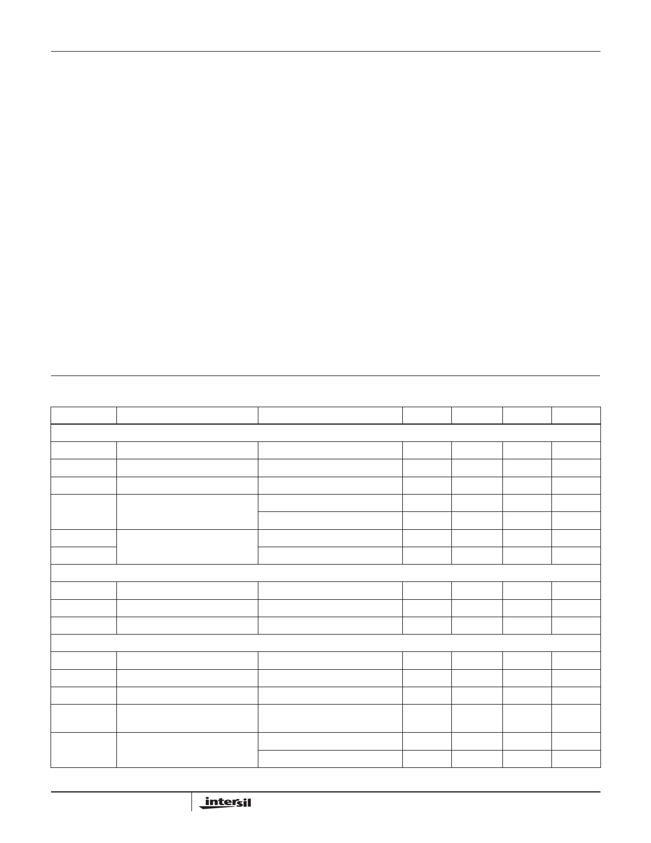
Electrical Specifications VIN = ENABLE = 5V, VDD1 = VDD2 = 14V, VGH = 25V, AVDD = 10V, TA = -40°C to 85°C
Unless Otherwise Noted.
SYMBOL
PARAMETER
TEST CONDITION
MIN
TYP
MAX
GENERAL
VS
VINInput Voltage Range
IS_DIS
VIN Supply Currents when Disabled ENABLE = 0V
IS
VIN Supply Currents
ENABLE = 5V, LX not switching
UVLO
Undervoltage Lockout Threshold VIN2 Rising
VIN2 Falling
OTR
Thermal Shutdown Temperature Temperature Rising
OTF
Temperature Falling
LOGIC INPUT CHARACTERISTICS - ENABLE, VFLK, FREQ, VDPM
2.7
3.3
5.5
0.2
2
1
2.3
2.45
2.6
2.2
2.35
2.5
140
100
VIL
Low Voltage Threshold
VIH
High Voltage Threshold
RIL
Pull-Down Resistor
STEP-UP SWITCHING REGULATOR
Enabled, Input at Vin
0.8
2.2
150
250
400
AVDD
∆AVDD/∆IOUT
∆AVDD/∆VIN
ACCAVDD
VFB
Output Voltage Range
Load Regulation
Line Regulation
Overall Accuracy (Line, Load,
Temperature)
Feedback Voltage (VFB)
VIN*1.25
50mA < ILOAD < 250mA
0.2
ILOAD = 150mA, 3.0 < VIN < 5.5V
0.15
10mA < ILOAD < 300mA,
-3
3.0 < Vin < 5.5V, 0°C < TA < 85°C
ILOAD = 100mA, TA = 25°C
1.20
1.21
ILOAD = 100mA, TA = -40°C to +85°C
1.19
1.21
20
0.25
3
1.22
1.23
UNIT
V
µA
mA
V
V
°C
°C
V
V
kΩ
V
%
%/V
%
V
V
3
FN9263.0
April 11, 2006
Share Link: 