ICS94206F-T Просмотр технического описания (PDF) - Integrated Circuit Systems
Номер в каталоге
Компоненты Описание
Список матч
ICS94206F-T Datasheet PDF : 18 Pages
| |||
ICS94206
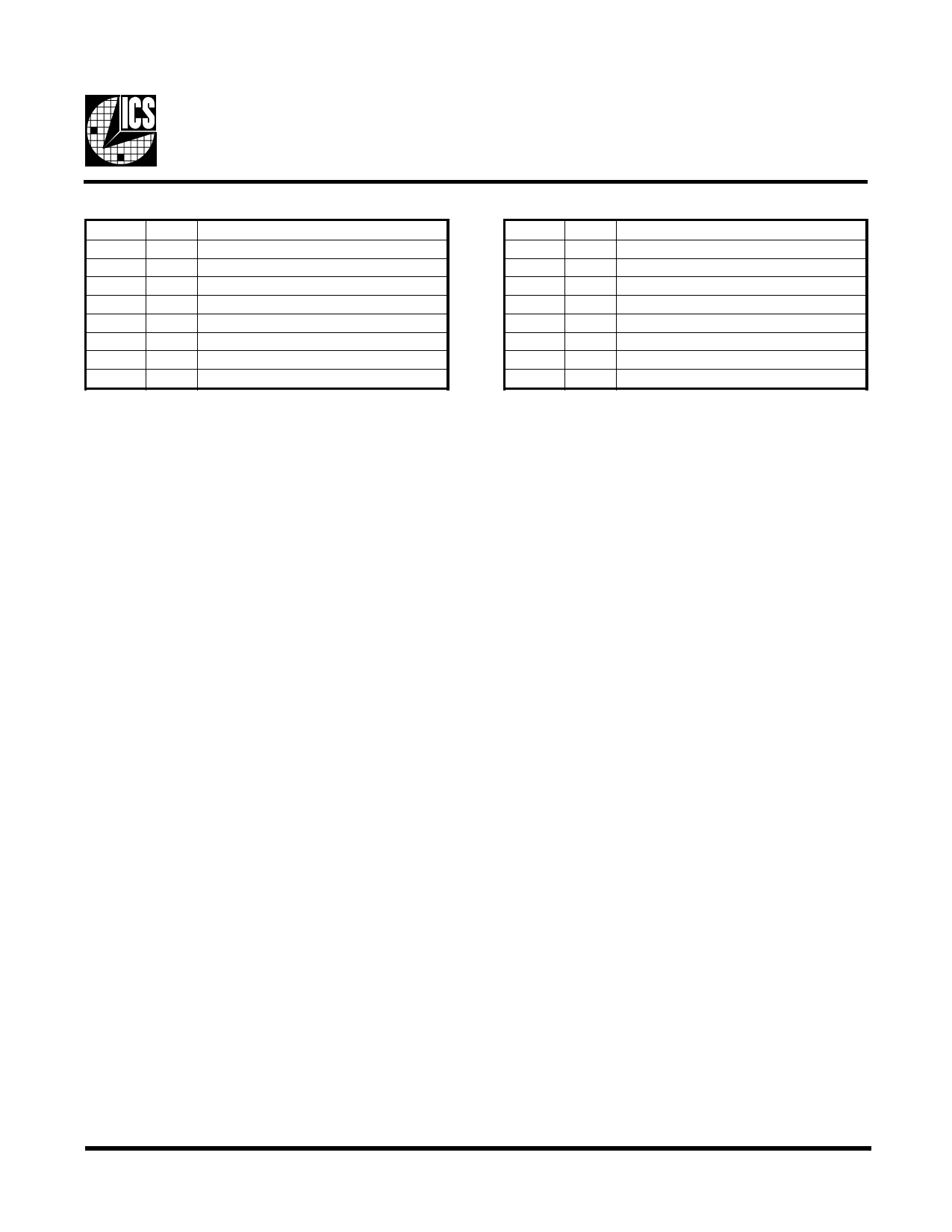
Byte 19: Reserved Register
Bit
Bit 7
Bit 6
Bit 5
Bit 4
Bit 3
Bit 2
Bit 1
Bit 0
PWD
X Reserved
X Reserved
X Reserved
X Reserved
X Reserved
X Reserved
X Reserved
X Reserved
Description
VCO Programming Constrains
VCO Frequency ...................... 150MHz to 500MHz
VCO Divider Range ................ 8 to 519
REF Divider Range ................. 2 to 129
Phase Detector Stability .......... 0.3536 to 1.4142
Useful Formula
VCO Frequency = 14.31818 x VCO/REF divider value
Phase Detector Stabiliy = 14.038 x (VCO divider value)-0.5
Byte 20: Reserved Register
Bit
Bit 7
Bit 6
Bit 5
Bit 4
Bit 3
Bit 2
Bit 1
Bit 0
PWD
X Reserved
X Reserved
X Reserved
X Reserved
X Reserved
X Reserved
X Reserved
X Reserved
Description
Note: Byte 19 and 20 are reserved registers, these are
unused registers writing to these registers will not
affect device performance or functinality.
To program the VCO frequency for over-clocking.
0. Before trying to program our clock manually, consider using ICS provided software utilities for easy programming.
1. Select the frequency you want to over-clock from with the desire gear ratio (i.e. CPU:SDRAM:3V66:PCI ratio) by
writing to byte 0, or using initial hardware power up frequency.
2. Write 0001, 1001 (19H) to byte 8 for readback of 21 bytes (byte 0-20).
3. Read back byte 11-20 and copy values in these registers.
4. Re-initialize the write sequence.
5. Write a '1' to byte 9 bit 7 and write to byte 11 & 12 with the desired VCO & REF divider values.
6. Write to byte 13 to 20 with the values you copy from step 3. This maintains the output spread, skew and slew rate.
7. The above procedure is only needed when changing the VCO for the 1st pass. If VCO frequency needed to be changed
again, user only needs to write to byte 11 and 12 unless the system is to reboot.
Note:
1. User needs to ensure step 3 & 7 is carried out. Systems with wrong spread percentage and/or group to group skew relation
programmed into bytes 13-16 could be unstable. Step 3 & 7 assure the correct spread and skew relationship.
2. If VCO, REF divider values or phase detector stability are out of range, the device may fail to function correctly.
3. Follow min and max VCO frequency range provided. Internal PLL could be unstable if VCO frequency is too fast or too slow.
Use 14.31818MHz x VCO/REF divider values to calculate the VCO frequency (MHz).
4. ICS recommends users, to utilize the software utility provided by ICS Application Engineering to program the VCO
frequency.
5. Spread percent needs to be calculated based on VCO frequency, spread modulation frequency and spreadamount desired. See
Application note for software support.
9
Share Link: 