DS1217M Просмотр технического описания (PDF) - Dallas Semiconductor -> Maxim Integrated
Номер в каталоге
Компоненты Описание
Список матч
DS1217M Datasheet PDF : 8 Pages
| |||
DS1217M
REMOTE CONNECTION VIA A RIBBON
CABLE
Existing systems which contain 28-pin bytewide sock-
ets can be retrofitted using a 28-pin DIP plug. The DIP
plug, AMP Part Number 746616-2, can be inserted into
the 28-pin site after the memory is removed. Connection
to the cartridge is accomplished via a 28-pin cable con-
nected to a 30-contact card edge connector, AMP Part
Number 499188-4. The 28-pin ribbon cable must be
right-justified, such that positions A1 and B1 are left dis-
connected. For applications where the cartridge is in-
stalled or removed with power applied, both ground con-
tacts (A1 and B1) on the card edge connector should be
grounded to further enhance data integrity. Access time
push-out may occur as the distance between the car-
tridge and the driving circuitry is increased.
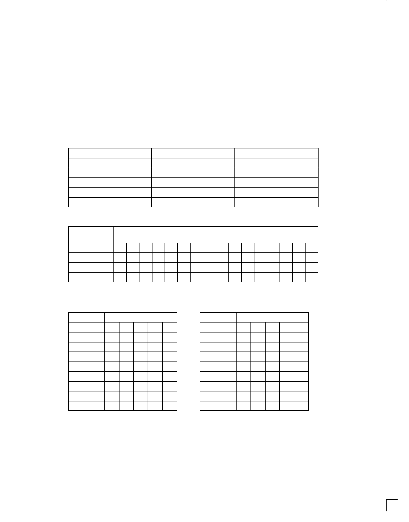
CARTRIDGE NUMBERING Table 1
PART NO.
DS1217M 1/2-25
DS1217M 1-25
DS1217M 2-25
DS1217M 3-25
DS1217M 4-25
DENSITY
64K x 8
128K x 8
156K x 8
384K x 8
512K x 8
NO. OF BANKS
2
4
8
12
16
ADDRESS INPUT PATTERN Table 2
ADDRESS
INPUTS
BIT SEQUENCE
0 1 2 3 4 5 6 7 8 9 10 11 12 13 14 15
A8
1 0 1 0 0 0 1 1 0 1 0XXXXX
A9
0101110011000011
A10
1010001101011100
A11
0101110010100011
X = See Table 3
BANK SELECT TABLE Table 3
BANK
A8 BIT SEQUENCE
SELECTED 11 12 13 14 15
BANKS OFF 0 X X X X
BANK 0
10000
BANK 1
10001
BANK 2
10010
BANK 3
10011
BANK 4
10100
BANK 5
10101
BANK 6
10110
BANK
BANK 7
BANK 8
BANK 9
BANK 10
BANK 11
BANK 12
BANK 13
BANK 14
BANK 15
A8 BIT SEQUENCE
10111
11000
11001
11010
11011
11100
11101
11110
11111
030598 3/8
Share Link: 