DS1090 Просмотр технического описания (PDF) - Maxim Integrated
Номер в каталоге
Компоненты Описание
Список матч
DS1090 Datasheet PDF : 9 Pages
| |||
DS1090
Low-Frequency, Spread-Spectrum EconOscillator
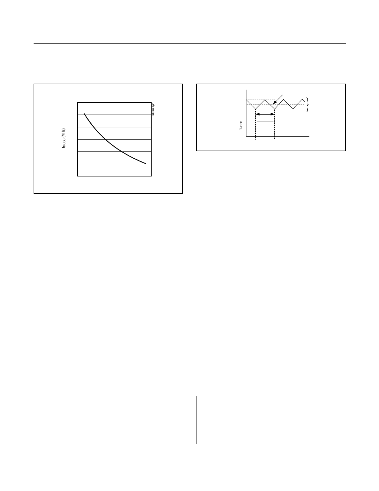
MASTER OSCILLATOR FREQUENCY vs.
EXTERNAL RESISTOR SELECTION
9
8
7
6
5
4
3
40 50
60
70 80
90
RSET RESISTANCE (kΩ)
Figure 1. Master Oscillator Frequency
Detailed Description
The DS1090 is a center-dithered, spread-spectrum silicon
oscillator for use as an external clock in reduced-EMI
applications. With a combination of factory-programmed
prescalers and a user-selected external resistor, output
frequencies from 125kHz to 8MHz can be achieved. The
output center frequency can be dithered by selecting the
desired dither rate and amplitude with discrete inputs J0,
J1, JC0, and JC1.
The DS1090 contains four basic circuit blocks: master
oscillator, factory-programmed prescaler, dither generator,
and the voltage-bias circuit that provides the feedback
path to the master oscillator for frequency control and
dithering functions.
Master Oscillator
The master oscillator is programmable in the application
by the use of an external resistor (RSET) tied to ground
(GND). Resistor values of 45kΩ to 91kΩ vary the
square-wave output frequency of the voltage-controlled
master oscillator (fMOSC) from 8MHz down to 4MHz
(see Figure 1).
The master oscillator (Hz) frequency can be stated as
fMOSC
≅
3.6461E+11
Resistor
(+ 1, 2, or 4% of fMOSC)
Programmed fMOSC
(- 1, 2, or 4% of fMOSC)
IF DITHER AMOUNT = 0%
DITHER
AMOUNT
(2, 4, OR 8%)
1
fMOD
TIME
Figure 2. Center Frequency Dither Diagram
Factory-Programmed Prescaler
The prescaler divides the frequency of the master oscillator
by 1, 2, 4, 8, 16, or 32 to generate the square-wave output
clock (fOSC). This divisor is factory-set and is an ordering
option.
Dither Generator
Spread-spectrum functionality is achieved by a user-
configurable divider (determines dither rate), a triangle
generator, and a user-configurable dither amplitude circuit
(see Block Diagram).
The input to the triangle-wave generator is derived
from the internal master oscillator and is fed through a
user-configurable divider. The settings of control pins JC0
and JC1 determine this dither rate divisor setting (see
Table 1), dividing the master clock by 4, 8, 16, or 32. The
clock signal is further divided by 128 in the triangle-wave
generator, which results in a triangle-wave signal of either
1/512th, 1/1024th, 1/2048th, or 1/4096th of the master
oscillator (fMOD), depending upon the user’s divisor set-
ting.
The dithering frequency can be also expressed as the
result of
fMOD
= fMOSC
Divisor ×128
where Divisor is 4, 8, 16, or 32.
Table 1. Dither Rate Divisor Settings
JC1
JC0
DITHERING PERCENTAGE
(fMOSC/n)
0
0
fMOSC /512
0
1
fMOSC /1024
1
0
fMOSC /2048
1
1
fMOSC /4096
DIVISOR
SETTING
4
8
16
32
www.maximintegrated.com
Maxim Integrated │ 7
Share Link: 