CS7666 Просмотр технического описания (PDF) - Cirrus Logic
Номер в каталоге
Компоненты Описание
Список матч
CS7666 Datasheet PDF : 42 Pages
| |||
CS7666
HIGH for READ packets. The master can read and
write to non-existent registers within the selected
device. WRITE operations will have no effect;
READ operations will return a value of 00h.
Station Address
Each device on the I2C bus has a unique 7-bit ad-
dress. An eighth bit, the R/W bit, determines if the
current data transfer writes data to the slave device
or reads data from the slave device. It is common to
represent the station address and R/W bit as two 8-
bit station addresses, one address for write accesses
and another address for read accesses. We will fol-
low this practice. The CS7666 default station ad-
dress is 34h for writes and 35h for reads. The
station address can be changed by writing a new
station address to register FFh. The value written to
this register does not include the R/W bit. For ex-
ample. The default station address (34h write / 35h
read) will be stored as 1Ah in register FFh.
Write Operations in Three-Byte Mode
The WRITE format consists of a three-byte packet.
The first byte is the station address with the data di-
rection bit set LOW to indicate a write. The second
byte is the device register address (0..255). The
third byte is the register data (0..255). No addition-
al bytes are allowed.
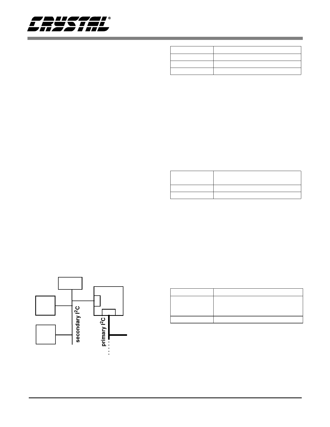
EPROM
CS7615
CS7666
CS4954
External
controller
To other sub-systems
Figure 7. I2C configuration showing primary
and secondary I2C busses.
Byte Sequence WRITE Format Packet Detail
First Byte
Station Address with LSB Set LOW
Second Byte Device Register Address (0..255)
Third Byte
Register Data (0..255)
Table 8. WRITE Format Packet
Address Set Operation
The ADDRESS SET format consists of a two-byte
packet which sets the address of a subsequent
READ operation. The first byte of the Station Ad-
dress with the LSB (data direction bit) set LOW to
indicate a write operation. The second byte is the
register address (0..255). The ADDRESS SET for-
mat is the same as the WRITE format, without the
register data (third byte).
Byte Sequence
ADDRESS SET format
Packet Details
First Byte
Station Address with LSB Set LOW
Second Byte Device Register Address (0..255)
Table 9. ADDRESS SET Format Packet Operation
Read Operations in Three-Byte Mode
The READ operation may consist of two or more
bytes. The first byte is the station address with the
LSB (data direction bit) set HIGH indicating a read
operation. The addressed device then sends one or
more bytes back from the register last addressed by
the previous WRITE operation or the previous AD-
DRESS SET operation.
Byte Sequence READ Format Packet Details
First Byte
Station Address with LSB set HIGH;
Source Device then Returns One
Byte of Register Data (0..255)
Second Byte Returned data from CS7666
Table 10. READ Format Packet.
Operating CS7666 in Four-Byte I2C Config-
uration
In this configuration the external controller talks
only to the CS7666 through the primary I2C inter-
face. All the other slave devices on the camera
DS302PP1
17
Share Link: 