CDB6422 Просмотр технического описания (PDF) - Cirrus Logic
Номер в каталоге
Компоненты Описание
Список матч
CDB6422 Datasheet PDF : 48 Pages
| |||
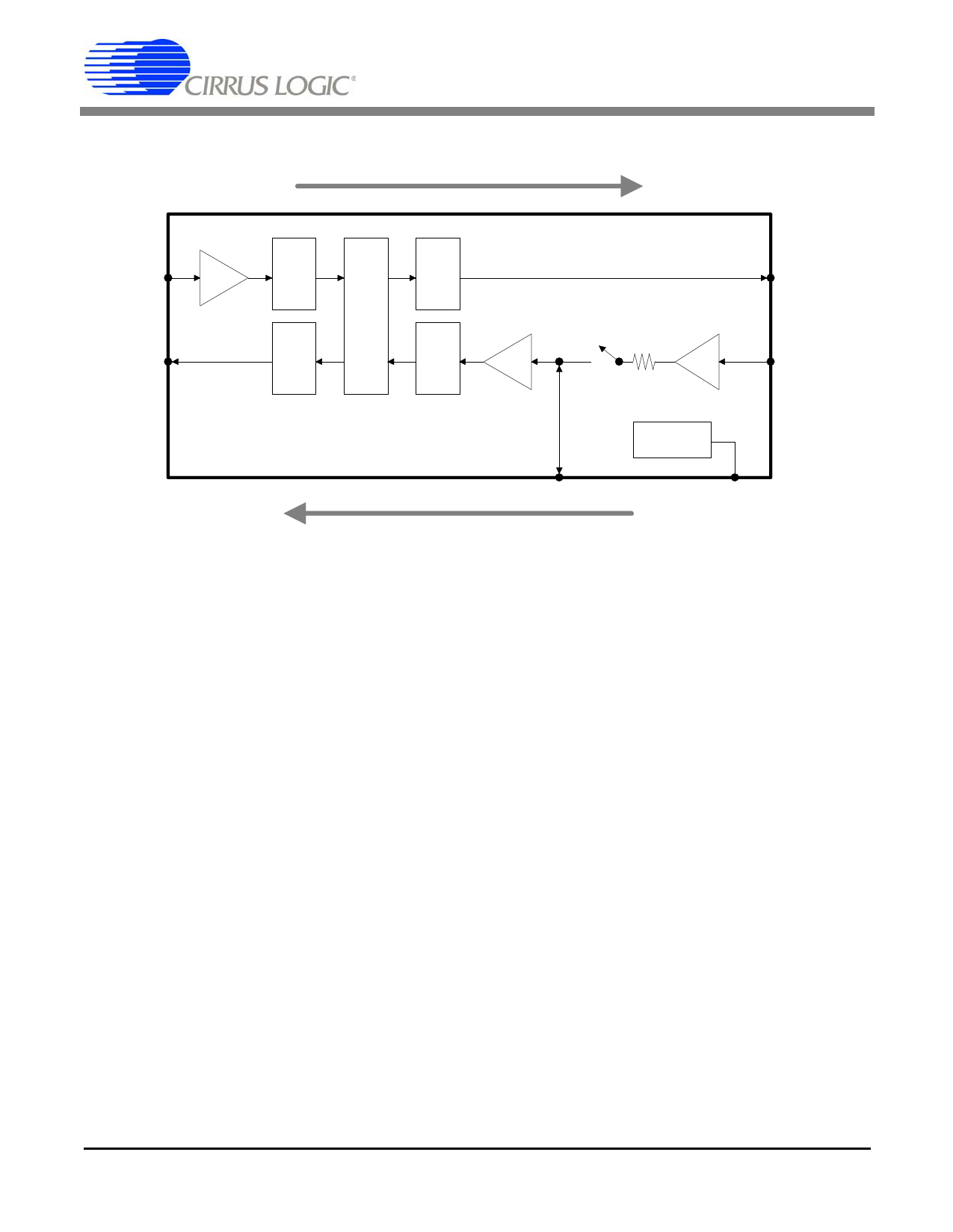
CS6422
Receive Path
NI 17 RGain
ADC
(0,6,9.5,12 dB)
FAR-END
NO 4
DAC
DAC
3 AO
D
S
P
ADC
TGain
Mic 1kΩ
NEAR-END
34 dB 20 API
(0,6,9.5,12 dB)
CS6422
Voltage
Reference
18
19
APO
MB
Transmit Path
Figure 6. Analog Interface
of higher amplitude will clip the ADC input and
will result in poor echo canceller performance. See
Section 4., “Design Considerations” for more de-
tails.
The outputs are delta-sigma digital to analog con-
verters (DACs) and have similar requirements to
the ADCs. The DACs are pre-compensated to ex-
pect a single-pole RC filter with a corner frequency
at 4 kHz. The full scale voltage output from a DAC
is 1.1 Vrms (3.1 Vpp) maximum, 1 Vrms typical, bi-
ased around 2.12 VDC.
3.1.1 Acoustic Interface
The pins API (pin 20), APO (pin 18), AO (pin 3),
and MB (pin 19) form the Acoustic Interface. A
block diagram of the Acoustic Interface is shown in
Figure 6.
API and APO are, respectively, the input and out-
put of the built-in microphone pre-amplifier. The
pre-amplifier is an inverting amplifier with a fixed
gain of 34 dB biased around an input offset voltage
of 2.12 V. APO is the output of the pre-amplifier
after a 1 kΩ (typical) resistor. The circuitry con-
nected to the amplifier input must present low
source impedance (<100 Ω) to the API pin or the
gain will be reduced. When using the internal mic
preamp, a 0.022 µF capacitor should be placed be-
tween APO and ground to provide the anti-aliasing
filter required by the ADC, as shown in Figure 4.
The pre-amplifier may be bypassed by clearing the
‘Mic’ bit (Register 0, bit 15) using the Microcontrol-
ler Interface (see Section 3.2, “Microcontroller Inter-
face”). If the internal mic preamp is not used, a
0.022 µF capacitor should be tied between API and
ground, and APO should be driven directly. In this
case, the signal into APO must be low-pass filtered
by a single-pole RC filter with a corner frequency at
8 kHz (see Figure 5).
Following the pre-amplifier is a programmable an-
alog gain stage, called TGain, which is controlled
DS295F1
11
Share Link: 