CMX625 Просмотр технического описания (PDF) - CML Microsystems Plc
Номер в каталоге
Компоненты Описание
Список матч
CMX625 Datasheet PDF : 34 Pages
| |||
ISDN TA POTS Interface
CMX625
Each channel consists of the following 4 bytes:
(i) The first two bytes consist of two 64kbps data channels, labelled ‘B1’ and ‘B2’, and transfer B channel
data to and from the network.
(ii) The third byte, labelled ‘Monitor’, is used for programming and controlling devices attached to the
IOM-2 interface. The data structure within the monitor channel is not defined and will be device
specific. The CMX625 is programmed via the monitor channel (see section 1.5.15).
(iii) In digital applications (ISDN line cards) the fourth byte contains two bits for the 16kbps ‘D’ channel,
four ‘Command/Indicate’ (C/I) bits for real time status information and two handshake bits for
supporting the handling of the monitor channel, labelled ‘MR’ and ‘MX’ (monitor transmit and receive).
The handshake procedure is described in section 1.5.4. In analogue applications (analogue line
cards) there is no 'D' channel in the fourth byte so the adjacent C/I channel is increased to 6 bits. The
C/I1 channel bits are used in the same way as for Terminal Mode.
1.5.4 Monitor Channel Handshake Protocol
The Monitor channel operates on an event driven basis. While data transfers on the bus take place
synchronised to the frame sync, the flow of data is controlled by a handshake procedure using the
outgoing MX (monitor transmit) and incoming MR (monitor receive) bits. Data is placed onto the monitor
channel and the MX bit is activated. This data will be transmitted repeatedly (once per 8kHz frame) until
the transfer is acknowledged (ACK) via the MR bit. The actual data rate is not fixed but is dependent upon
the response speed of the transmitter and receiver. The protocol is applicable to both TE and non-TE
modes.
MX
EOM
Data
Byte 1
Byte 2
Byte 3
Byte n
MR
125µs
ACK
ACK
ACK
ACK
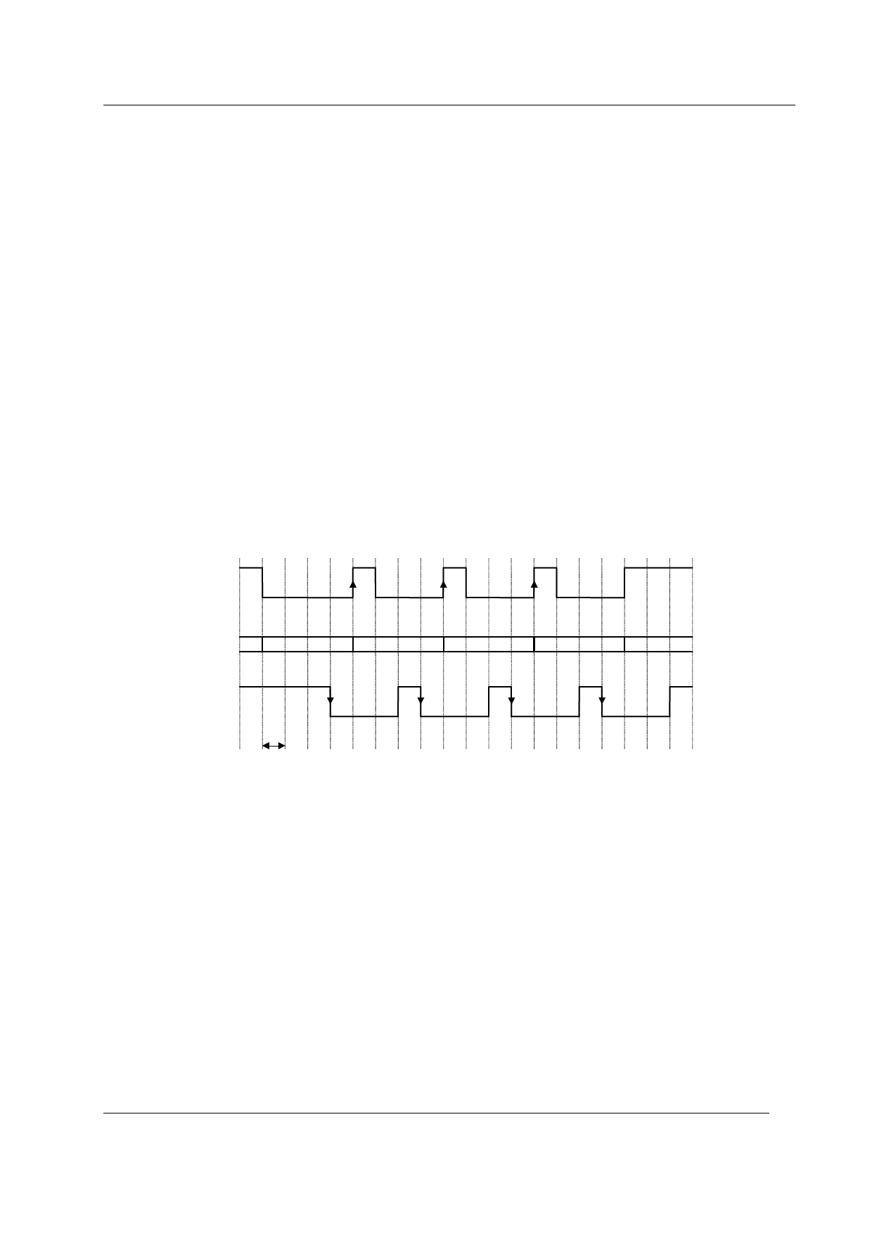
Figure 5 Monitor Handshake Timing (general case)
Figure 5 shows the general case for monitor handshake timing. The first byte of data is placed on the bus
and MX is activated (low). MX remains active and the data remains valid until an inactive-to-active
transition of MR is received, indicating that the receiver has read the data off the bus. The next byte is
placed on the bus after the inactive-to-active transmission of MR, as early as the next frame (there is no
limit to the maximum number of frames). At the time that the second byte is transmitted, MX is returned
inactive (high) for one frame (MX inactive for more than one frame indicates an End of Message). In
response to MX going active (low), MR will be deactivated (high) for one frame (the MX inactive to MR
inactive delay can be any number of frames). This procedure is repeated for each additional byte. The
transmitter sends an End of Message (EOM), after the last byte of data has been transmitted, by not
reactivating MX after deactivating it.
The receiver can hold off the transmitter by keeping MR active until the receiver is ready for the next byte.
The transmitter will not start the next transmission cycle until MR goes inactive.
The transmitter is able to abort a transmission by holding MX inactive (high) for two or more frames, this
will generate an interrupt when the INTERRUPT MASK Register bit 3 is unmasked (logic ‘1’) and bit 3 of
the Status Register will be set to ‘1’.
2001 Consumer Microcircuits Limited
11
D/625/2
Share Link: 