CMX625 Просмотр технического описания (PDF) - CML Microsystems Plc
Номер в каталоге
Компоненты Описание
Список матч
CMX625 Datasheet PDF : 34 Pages
| |||
ISDN TA POTS Interface
CMX625
(v) The ‘Intercommunication Channel’ consists of two 64kbps data channels, labelled IC1 and IC2, and
provide additional communications paths between devices other than the layer 1 device (data to and
from the layer 1 device is transferred over the B channels).
(vi) The ‘TIC’ (Terminal IC) bus is used for connecting more than one device to the D and C/I0 channels
in Channel 0. The TIC bus is not used by the CMX625.
1.5.3 Non-Terminal Mode (non-TE)
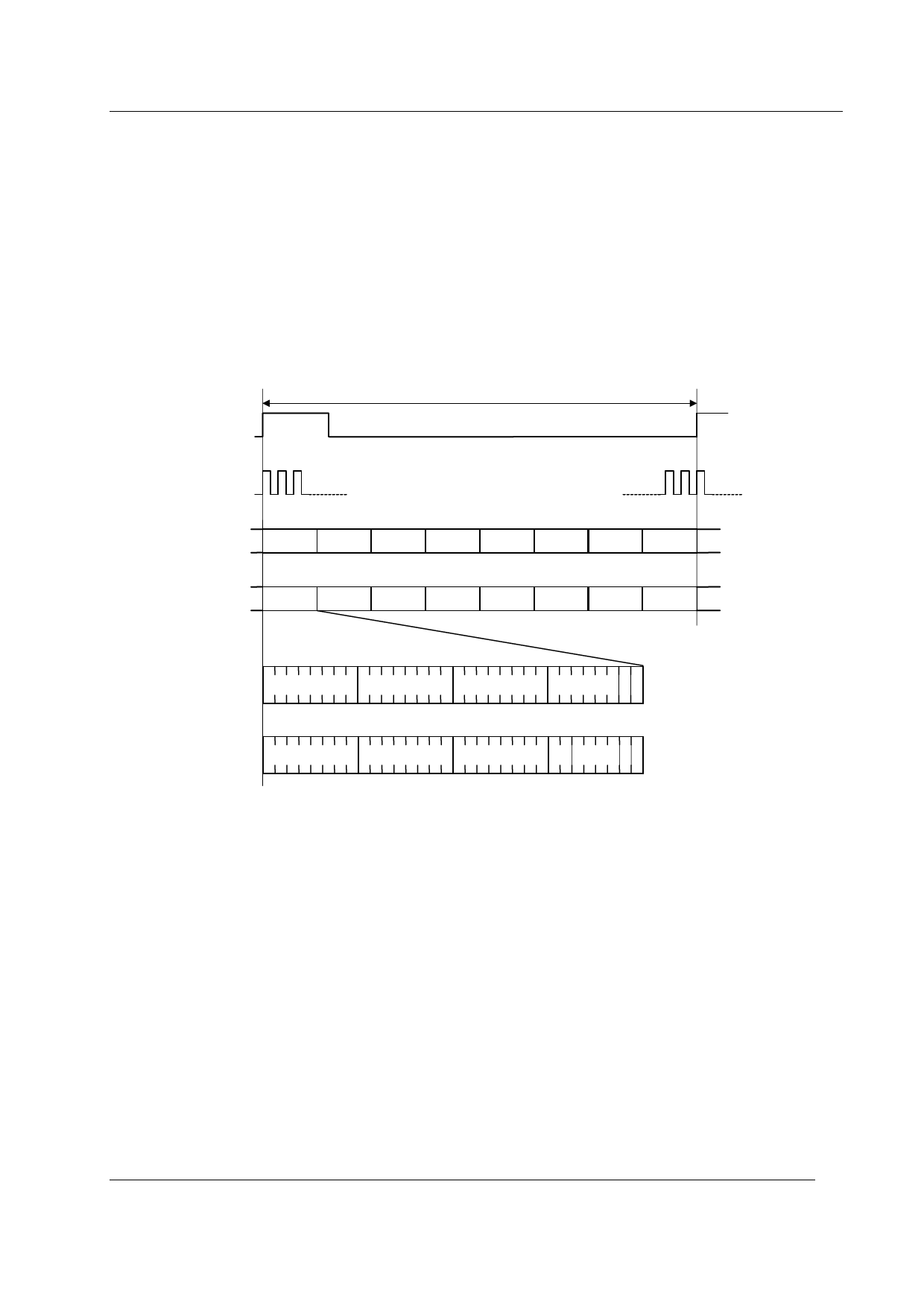
The non-TE mode (Line Card Mode) frame structure consists of up to 8 channels of 4 bytes each repeated
at 8kHz, i.e. 256 bits in 125µs or a data rate of 2048kbps for 8 channel frames. The Data Clock (DCL)
operates at twice the data rate, i.e. 4.096MHz. Figure 4 shows the non-TE mode frame structure.
FSC
125µs
DCL
DD
CH0 CH1 CH2 CH3 CH4 CH5 CH6 CH7 CH0
DU
CH0 CH1 CH2 CH3 CH4 CH5 CH6 CH7 CH0
B1
B2
M
L
S MONITOR S
C/I
MM
R X for analogue lines
B
B
B1
B2
M
L
S MONITOR S D
C/I
MM
RX
for ISDN lines
B
B
FSC = 8kHz
DCL = 4.096MHz
DD, DU = 2048kbps
Figure 4 Non-Terminal Mode Frame Structure
In non-TE mode the IOM-2 bus time multiplexes data, control and status information for up to eight IOM-2
devices or up to 16 Codec-Filters over a single full duplex interface. The frames are subdivided into 8
channels, with one channel being dedicated to each IOM-2 device or pair of Codecs.
Each device on the IOM-2 bus is assigned a slot address and only transmits to and receives from that time
slot. Pins SA0, SA1 and SA2 on the CMX625 are used to program the Slot Address. Outside the
allocated slot the transmit drivers will be set to high impedance to allow other devices to transmit in their
own time slot. To allow two CMX625 devices to share the same slot a Device Select pin (DS) is made
available. This pin forms part of the Monitor Channel Address Byte along with the Slot Address pins and
allows either of the two devices sharing a slot to be individually addressed. See section 1.5.2, part (ii)
MON Channel Address Byte. This mechanism allows both the B1 and B2 data from the same time slot to
be utilised by different devices.
2001 Consumer Microcircuits Limited
10
D/625/2
Share Link: 