AM7990 Просмотр технического описания (PDF) - Advanced Micro Devices
Номер в каталоге
Компоненты Описание
Список матч
AM7990 Datasheet PDF : 27 Pages
| |||
ALS Driver or
Equivalent
X1
03378I-7
Figure 3. TTL Clock Driver Circuit for X1
SIA Oscillator
Specification for External Crystal
When using a crystal to drive the Am7992B oscillator,
the following crystal specification should be used to en-
sure a transmit accuracy of 0.01%:
Resonant Frequency
Error with CL = 50 pF
Change in Resonant
Frequency Temperature
with CL = 50 pF
Parallel Resonant
Frequency with
CL = 50 pF
Motional Crystal
Capacitance, C1
Limit
Min Nominal Max
–50
0
+50
–40
+40
20
0.022
Unit
PPM
PPM
MHz
pF
Some crystal manufacturers have generated crystals
to this specification. One such manufacturer is Reeves-
Hoffman. Their ordering part number for this crystal is
RH#04-20423-312. Another manufacturer is Epson—
Par t #MA 506-200M-50 pF, which is a surface-
mounted crystal.
Specification for External TTL Level
When driving the oscillator from an external clock
source, X2 must be left floating (unconnected). An
external clock having the following characteristics
must be used to ensure less than +0.5 ns jitter at
Transmit+ (see the X1 Driven from External Source
waveform diagram and the TTL Clock Driver Circuit
for X1, Figure 3):
s Clock Frequency: 20 MHz ±0.01%
s Rise/Fall Time (tR/tF): <4 ns, monotonic
s X1 HIGH/LOW Time (tHlGH/tLOW): > 20 ns
s X1 Falling Edge-to-Falling Edge Jitter: < ±0.2 ns at
1.5 V input
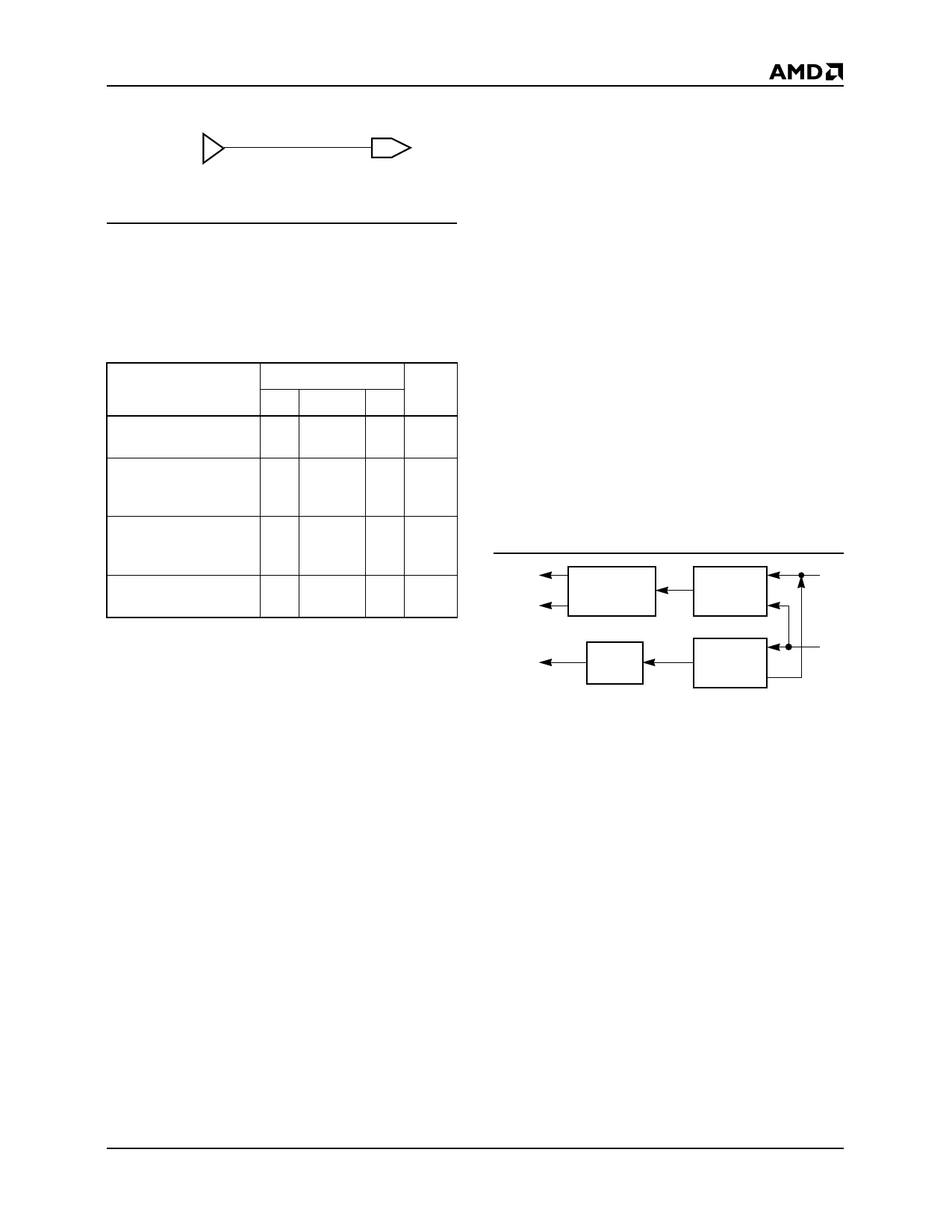
Receiver Path
The principle functions of the receiver are to signal the
LANCE that there is information on the receive pair and
to separate the incoming Manchester-encoded data
stream into clock and NRZ data.
The receiver section (see Figures 4 and 5) consists of
two parallel paths. The receive data path is a zero
threshold, wide bandwidth line receiver. The carrier
path is an offset threshold bandpass-detecting line re-
ceiver. Both receivers share common bias networks to
allow operation over an input common mode range of
0 V to 5.5V.
RX
RCLK
RENA
Manchester
Decoder
Data
Receiver
Carrier
Detect
Noise
Reject
Filter
Figure 4. Receiver
DI±
03378I-8
Am7992B
7
Share Link: 