AD73460 Просмотр технического описания (PDF) - Analog Devices
Номер в каталоге
Компоненты Описание
Список матч
AD73460 Datasheet PDF : 32 Pages
| |||
AD73460
VINP1
VINN1
VINP2
VINN2
SIGNAL
CONDITIONING
0/38dB
PGA
SIGNAL
CONDITIONING
0/38dB
PGA
ANALOG
⌺-⌬
MODULATOR
ANALOG
⌺-⌬
MODULATOR
DECIMATOR
DECIMATOR
VINP3
VINN3
REFCAP
REFOUT
VINP4
VINN4
SIGNAL
CONDITIONING
0/38dB
PGA
ANALOG
⌺-⌬
MODULATOR
DECIMATOR
REFERENCE
AFE SECTION
SIGNAL
CONDITIONING
0/38dB
PGA
ANALOG
⌺-⌬
MODULATOR
DECIMATOR
VINP5
VINN5
SIGNAL
CONDITIONING
0/38dB
PGA
ANALOG
⌺-⌬
MODULATOR
DECIMATOR
VINP6
VINN6
SIGNAL
CONDITIONING
0/38dB
PGA
ANALOG
⌺-⌬
MODULATOR
DECIMATOR
AD73460
SDI
SDIFS
SCLK2
SERIAL
I/O
PORT
ARESET
AMCLK
SE
SDO
SDOFS
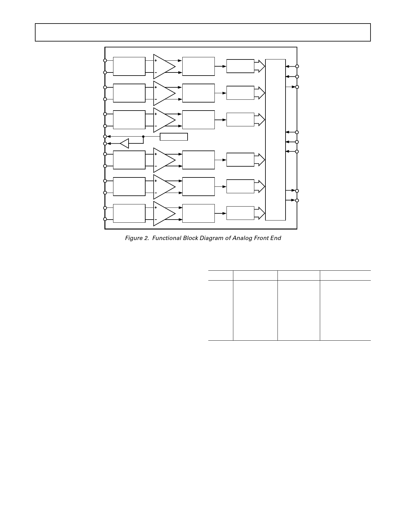
Figure 2. Functional Block Diagram of Analog Front End
FUNCTIONAL DESCRIPTION—AFE
Encoder Channel
Each encoder channel consists of a signal conditioner, a switched
capacitor PGA, and a sigma-delta analog-to-digital converter
(ADC). An on-board digital filter, which forms part of the
sigma-delta ADC, also performs critical system-level filtering.
Due to the high level of oversampling, the input antialias require-
ments are reduced such that a simple single pole RC stage is
sufficient to give adequate attenuation in the band of interest.
Signal Conditioner
Each analog channel has an independent signal conditioning
block. This allows the analog input to be configured by the user
depending on whether differential or single-ended mode is used.
Programmable Gain Amplifier
Each encoder section’s analog front end comprises a Switched
Capacitor PGA that also forms part of the sigma-delta modulator.
The SC sampling frequency is DMCLK/8. The PGA, whose
programmable gain settings are shown in Table II, may be used
to increase the signal level applied to the ADC from low output
sources such as microphones, and can be used to avoid placing
external amplifiers in the circuit. The input signal level to the
sigma-delta modulator should not exceed the maximum input
voltage permitted.
The PGA gain is set by bits IGS0, IGS1, and IGS2 in control
Registers D, E, and F.
Table II. PGA Settings for the Encoder Channel
IxGS2
0
0
0
0
1
1
1
1
IxGS1
0
0
1
1
0
0
1
1
IxGS0
0
1
0
1
0
1
0
1
Gain (dB)
0
6
12
18
20
26
32
38
ADC
Each channel has its own ADC consisting of an analog sigma-
delta modulator and a digital antialiasing decimation filter. The
sigma-delta modulator noise-shapes the signal and produces
1-bit samples at a DMCLK/8 rate. This bit stream, representing
the analog input signal, is input to the antialiasing decimation
filter. The decimation filter reduces the sample rate and increases
the resolution.
REV. A
–11–
Share Link: 