AD8341 Просмотр технического описания (PDF) - Analog Devices
Номер в каталоге
Компоненты Описание
Список матч
AD8341 Datasheet PDF : 20 Pages
| |||
AD8341
THEORY OF OPERATION
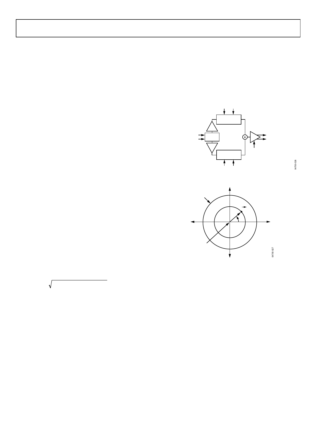
The AD8341 is a linear RF vector modulator with Cartesian
baseband controls. In the simplified block diagram given in
Figure 26, the RF signal propagates from the left to the right
while baseband controls are placed above and below. The RF
input is first split into in-phase (I) and quadrature (Q) compo-
nents. The variable attenuators independently scale the I and Q
components of the RF input. The attenuator outputs are then
summed and buffered to the output.
By controlling the relative amounts of I and Q components that
are summed, continuous magnitude and phase control of the
gain is possible. Consider the vector gain representation of the
AD8341 expressed in polar form in Figure 27. The attenuation
factors for the I and Q signal components are represented on
the x- and y-axis, respectively, by the baseband inputs, VBBI and
VBBQ. The resultant of their vector sum represents the vector
gain, which can also be expressed as a magnitude and phase. By
applying different combinations of baseband inputs, any vector
gain within the unit circle can be programmed.
A change in sign of VBBI or VBBQ can be viewed as a change in
sign of the gain or as a 180° phase change. The outermost
circle represents the maximum gain magnitude of unity. The
circle origin implies, in theory, a gain of 0. In practice, circuit
mismatches and unavoidable signal feedthrough limit the
minimum gain to approximately −34.5 dB. The phase angle
between the resultant gain vector and the positive x-axis is de-
fined as the phase shift. Note that there is a nominal, systematic
insertion phase through the AD8341 to which the phase shift is
added. In the following discussions, the systematic insertion
phase is normalized to 0°.
The correspondence between the desired gain and phase set-
points, GainSP and PhaseSP, and the Cartesian inputs, VBBI and
VBBQ, is given by simple trigonometric identities
[ ( ) ] GainSP = (VBBI /VO )2 + VBBQ /VO 2
( ) PhaseSP = arctan VBBQ /VBBI
where:
VO is the baseband scaling constant (500 mV).
VBBI and VBBQ are the differential I and Q baseband voltages,
respectively.
Note that when evaluating the arctangent function, the proper
phase quadrant must be selected. For example, if the principal
value of the arctangent (known as the Arctangent(x)) is used,
quadrants 2 and 3 could be interpreted mistakenly as quadrants
4 and 1, respectively. In general, both VBBI and VBBQ are needed
in concert to modulate the gain and the phase.
Pure amplitude modulation is represented by radial movement
of the gain vector tip at a fixed angle, while pure phase modula-
tion is represented by rotation of the tip around the circle at a
fixed radius. Unlike traditional I-Q modulators, the AD8341 is
designed to have a linear RF signal path from input to output.
Traditional I-Q modulators provide a limited LO carrier path
through which any amplitude information is removed.
VBBI
I CHANNEL INPUT
LINEAR
ATTENUATOR
SINGLE-ENDED OR
DIFFERENTIAL
50Ω INPUT Z
V-I
0°/90°
V-I
LINEAR
ATTENUATOR
Q CHANNEL INPUT
VBBQ
SINGLE-ENDED OR
I-V
DIFFERENTIAL
50Ω OUTPUT
OUTPUT
DISABLE
Figure 26. Simplified Architecture of the AD8341
Vq
MAX GAIN
+0.5
A
|A|
θ
–0.5
+0.5 Vi
MIN GAIN
–0.5
Figure 27. Vector Gain Representation
RF QUADRATURE GENERATOR
The RF input is directly coupled differentially or single-ended
to the quadrature generator, which consists of a multistage RC
polyphase network tuned over the operating frequency range of
1.5 GHz to 2.4 GHz. The recycling nature of the polyphase net-
work generates two replicas of the input signal, which are in
precise quadrature, i.e., 90°, to each other. Since the passive
network is perfectly linear, the amplitude and phase information
contained in the RF input is transmitted faithfully to both chan-
nels. The quadrature outputs are then separately buffered to
drive the respective attenuators. The characteristic impedance
of the polyphase network is used to set the input impedance of
the AD8341.
Rev. 0 | Page 10 of 20
Share Link: 