ZR36057 Просмотр технического описания (PDF) - Zoran Corporation
Номер в каталоге
Компоненты Описание
Список матч
ZR36057 Datasheet PDF : 48 Pages
| |||
Enhanced PCI Bus Multimedia Controller
5.5.4 Connecting The ZR36057 To The ZR36050
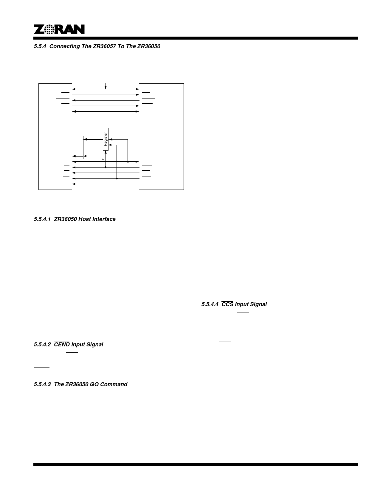
Figure 8 shows the recommended connection of the ZR36057 to
the ZR36050.
ZR36050
CLK_IN
CCS
CBUSY
END
CODE[7:0]
ZR36057
VCLKx2
CCS
CBUSY
CEND
CODE[7:0]
ADDR[9:0]
DATA[7:0]
n+1
CS
RD
WR
RESET
GADD
GDAT[7:0]
GCSn
GRD
GWR
GPIOn
Figure 8. ZR36057 to ZR36050 Connections
5.5.4.1 ZR36050 Host Interface
The host interface of the ZR36050 is controlled by the ZR36057
as one of the guests. The recommended guest timing parame-
ters are Tdur=12, Trec=3. An external register must be added in
order to support access to the entire ZR36050 internal memory
space. This external register is controlled by the ZR36057 as an
additional guest.
One basic host access to the ZR36050 internal memory via the
ZR36057 is performed using two successive guest bus access-
es. The first is to the external address register during which the
GDAT bus holds (for example) the 8 Lsb’s of the ZR36050
internal memory address. The second is the command itself
during which the GDAT bus holds the data to be written to the
ZR36050 internal memory and the 2 Msb’s of the address are
driven by GADD[1..0].
5.5.4.2 CEND Input Signal
Assertion of END by the ZR36050 indicates the end of a field
process in compression or decompression. This is latched as
CEND in the Codec Interface.
5.5.4.3 The ZR36050 GO Command
The GO command signals the ZR36050 to start a compression
or decompression process. The GO command is performed
automatically by the ZR36057, by writing to address 0x00h of
the ZR36050 internal memory. The host software is responsible
for pre-loading this address to the external address register after
the completion of ZR36050 initialization.
The ZR36057 uses the JPEGuestID and the JPEGuestReg
parameters for the GO command guest address.
In Motion Video Compression mode, the first GO command is
initiated by the host after finishing the initialization of all the
peripheral devices. After the first field, the GO command is
executed after the code of the previous field has been trans-
ferred to the system memory.
In Decompression mode, the GO command is executed only
after the Code FIFO has been filled from the relevant system
memory code buffer.
Important Note:
The automatic GO command is enabled by the Go_En register
bit, in the JPEG Mode and Control Register. If the host software
tries to execute a PostOffice cycle while Go_En is set to ‘1’
(enabled), the PostOffice cycle may not be executed correctly.
Therefore, Go_En must be disabled during PostOffice accesses.
The following is the sequence of actions required for a Post
Office access or series of accesses:
• Disable the Go_En bit.
• Wait at least 15 PCI clock cycles to allow the currently exe-
cuting GO command, if there is one, to be completed.
• Execute the PostOffice access, or the series of accesses.
• Enable the Go_En bit (at least for 5 PCI clocks).
If an internal GO command is requested while Go_En is dis-
abled, it is stored internally, and executed when Go_En is
enabled again.
Note that there is a trade-off between the “chunk” size of a series
of PostOffice accesses and the delay imposed on the ZR36050
GO command. Using a large chunk size reduces the overhead
resulting from the need to toggle Go_En, but delaying the GO
command too much can prevent the next field process from exe-
cuting correctly.
5.5.4.4 CCS Input Signal
The ZR36050 CCS signal designates the start of a code trans-
action. It stays active until the end of the transaction. In
Compression mode, the ZR36057 uses CCS to enable the
sampling of the incoming code stream. In Decompression mode,
it uses CCS to enable the drive of the code stream.
5.6 I2C Bus Interface
The I2C port of the ZR36057 consists of a clock signal, SCK, and
data signal, SDA. Both have two possible levels: active low or
passive tri-state. This configuration lets the ZR36057 be the only
master of an I2C clock. Both lines must be pulled-up externally.
By accessing the I2C application-specific register bits appropri-
ately, the host software can generate valid I2C start and stop
conditions, write address and write or read data one bit at a time.
5.7 General Purpose I/O Pins
The ZR36057 has 8 general purpose I/O pins, fully controlled by
the host. Each of these pins can be separately configured as
17
Share Link: 