ZR36050 Просмотр технического описания (PDF) - Unspecified
Номер в каталоге
Компоненты Описание
Список матч
ZR36050 Datasheet PDF : 52 Pages
| |||
ADVANCE INFORMATION
ZR36050
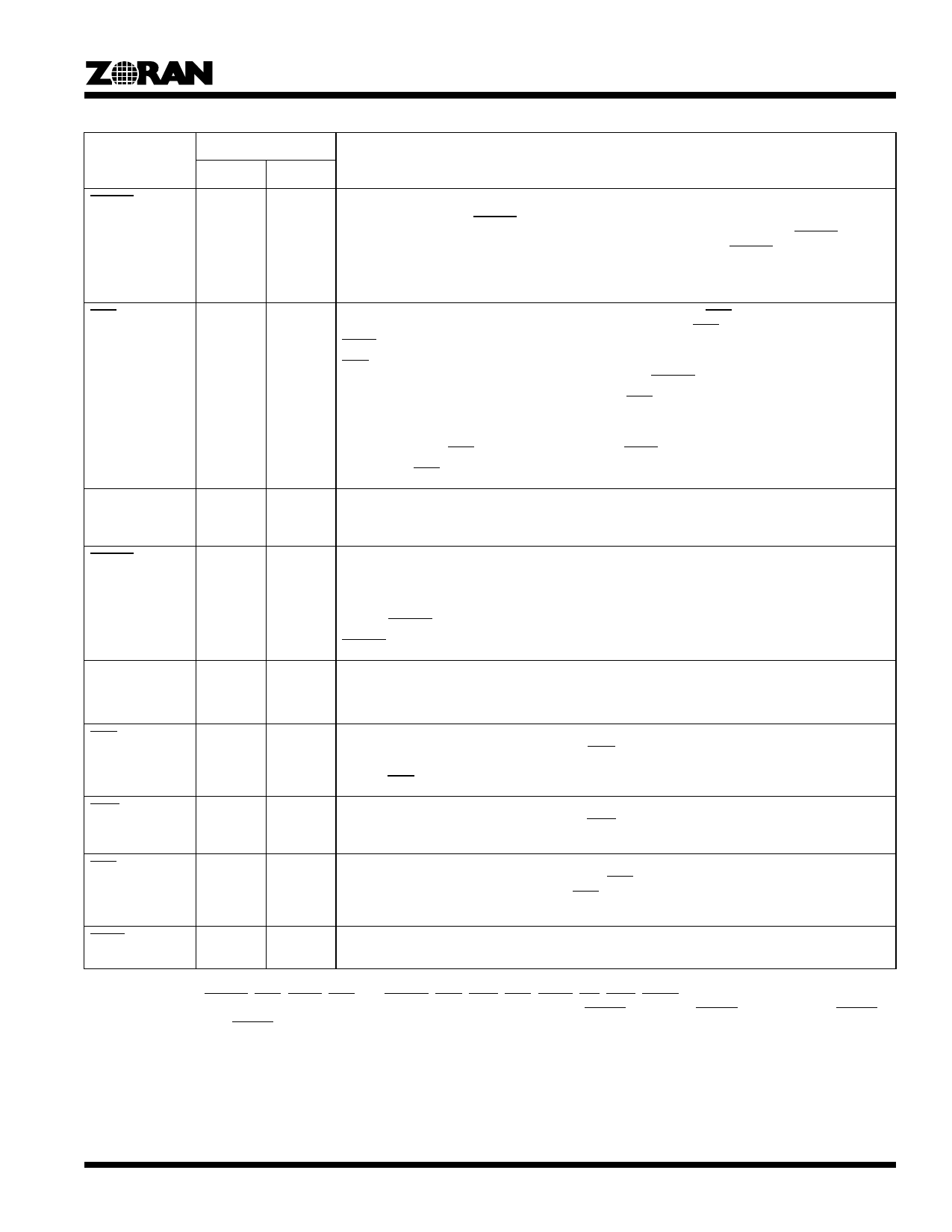
Table 1. Signal Description1, 2 (Continued)
Type3
Signal
Encode Decode
Description
DSYNC
I
O
Data Synchronization. This active- low signal is an input in encoding and output in decoding modes.
In the encoding modes, DSYNC marks the start of an 8x8 image data block and should appear as an
input one CLK_IN before the first image data of a block. In the decoding modes, DSYNC is output
one CLK_IN before the first image data sample of a block. The width of DSYNC is one CLK_IN cycle.
In the Fast Preview mode, and the Lossless encoding and decoding modes, this signal precedes
each image data sample.
EOS
I
O
End Of Scan. This active-low signal is an input in encoding modes. EOS indicates the last image data
sample of each scan entering the ZR36050. In encoding modes, EOS must be input regardless of the
STOP signal.
EOS is an output signal in the decoding mode. It is generated together with the last image data
sample of each scan leaving the ZR36050. In this case, DSYNC will not be issued.
In the Fast Preview and Lossless decoding modes, EOS is output within 64 CLK_IN cycles after the
last sample of a scan. It is merely used in as an indication of the completion of the current process
without having any timing significance.
In decoding mode, EOS is output regardless of the STOP signal.
The width of EOS is one CLK_IN cycle.
COEF(10-0)
O
O
Coefficient Bus. This 11-bit output bus is used to transfer DCT coefficients out of the device in the
encoding and decoding modes. The DCT coefficients are output in column-major order. This bus is
not used in the Fast Preview and Lossless encoding and decoding modes.
CSYNC
O
O
Coefficient Synchronization. This active-low signal indicates the beginning of an 8x8 DCT coefficient
block.
In the encoding and decoding modes, this signal is generated by the ZR36050. It is asserted one
CLK_IN cycle before the first coefficient of a block is placed on the COEF bus by the ZR36050. The
width of CSYNC is one CLK_IN cycle.
CSYNC is not used in the Fast Preview and Lossless encoding and decoding modes.
CODE(7-0)
O
I
Code. In Master mode Compressed Data Transfer, this 8-bit bidirectional bus is used to read the com-
pressed data from or write to the Compressed Data Memory.
In the 16-bit Slave and DMA modes, this bus is used as an extension of the DATA bus.
COE
-
O
Compressed Data Memory Read. This active-low output signal acts as a read pulse from the
ZR36050 to the Compressed Data Memory. COE goes active 0.5 CLK_IN cycles after the start of a
read cycle and remains active until the end of the read cycle. The CODE bus is latched on the rising
edge of COE.
CWE
O
-
Compressed Data Memory Write. This active-low output signal acts as a write pulse from the
ZR36050 to the Compressed Data Memory. CWE goes active 0.5 CLK_IN cycles after the start of a
write cycle and remains active until the end of the write cycle.
CCS
O
O
Compressed Data Memory Chip Select. This active-low output signal acts as a chip select signal from
the ZR36050 to the Compressed Data Memory. CCS goes active at the start of a read or write cycle
and remains active throughout the cycle. CCS remains active continuously in back to back read or
write cycles. The length of a read or write cycle can be from one to eight CLK_IN periods.
CAEN
O
O
Address Counter Enable. This active-low output signal can be used to advance an external Com-
pressed Data Memory address counter.
1. The DATA, CODE, PIXEL, and COEF buses have internal pull-downs that provide 50 microamps of pull-down current at 0.4 volts.
2. The control pins: DSYNC, EOS, STOP, END, CL, CSYNC, COE, CWE, CCS, CAEN, INT, DINT, DREQ and COMP, have internal pull-up
devices that provide 50 microamps at 2.4 volts. These pull-ups are turned on only when STDBY is active but RESET is inactive. When STDBY
is active together with RESET, the above control pins float.
3. I = Input, O = Output, B = Bidirectional, S = Supply.
5
Share Link: 