UAA2062 Просмотр технического описания (PDF) - Philips Electronics
Номер в каталоге
Компоненты Описание
Список матч
UAA2062 Datasheet PDF : 40 Pages
| |||
Philips Semiconductors
Analog cordless telephone IC
Product specification
UAA2062
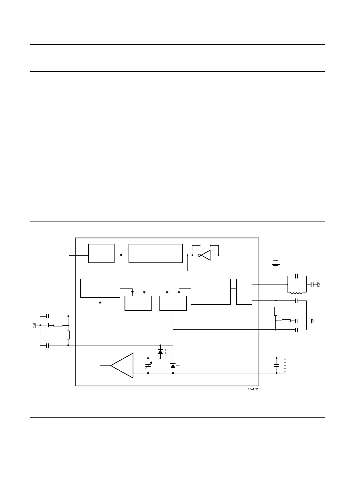
The synthesizer
The synthesizer has been designed to support most
country channel frequencies between 25 and 50 MHz
(see Chapter “Channel frequencies”).
The local oscillator LO2 and the reference divider provide
the reference frequency for the RX and TX PLL loops.
A single bit programmes the divider value for the reference
divider. A 5 kHz reference frequency (respectively
12.5 kHz) is used with a 10.24 MHz crystal frequency
(respectively 11.15 MHz). The clock divider ratio can be
programmed to 2.5 or to 80. The ratio 80 can be chosen
when the IC is in sleep mode to obtain current saving in the
microcontroller. The clock output is a CMOS output
inverter, supplied by Vref(PLL).
The 14-bit TX counter is programmed for the desired
transmit channel frequency. The 14-bit RX counter is
programmed for the desired RX VCO frequency.
All counters power-up in the proper default state and for a
10.24 MHz reference crystal. Both RX and TX phase
detectors have current drive type outputs of 400 µA.
The RX VCO is connected to an external capacitor and
inductor as illustrated in Fig.5. The varicaps are integrated.
Operating in the 25 US channels, there is a large
frequency difference between the minimum and the
maximum channel frequencies. The sensitivity of the
RX VCO is not large enough to accommodate this large
frequency range. Internal programmable capacitors can
be connected across the RX VCO tank circuit to change
the RX VCO sensitivity. The TX VCO also has internal
programmable capacitors to accommodate a large
frequency range. Chapter “Channel frequencies” shows
the frequency selection for all countries.
andbook, full pagewidth
CLKO 22
CLOCK
DIVIDER
1-BIT PROGRAMMABLE
REFERENCE COUNTER
/2048 or /892
crystal oscillator
14-BIT
PROGRAMMABLE
RX COUNTER
C1
RXPD 47
R2
C2
R3
43
C3
RXLF
RX PHASE
DETECTOR
TX PHASE
DETECTOR
14-BIT
PROGRAMMABLE
TX COUNTER
RX VCO
24 LO2I
23 LO2O
9 LO3I
TX
VCO
3 TXLF
R6
2 TXPD
44 LO1I
45 LO1O
C6
R5 C5
C4
Fig.5 Synthesizer schematic diagram.
FCA123
2000 Aug 10
9
Share Link: 