AMS2026 Просмотр технического описания (PDF) - Advanced Monolithic Systems Inc
Номер в каталоге
Компоненты Описание
Список матч
AMS2026 Datasheet PDF : 5 Pages
| |||
APPLICATION HINTS
Power Supply Considerations
A 0.047µF ceramic bypass capacitor close to the device, between
input and ground is recommended. When the output load is heavy
or has large paralleled capacitors, a high value electrolytic
capacitor should be used. To improve the immunity of the device to
ESD, use a 0.1µF ceramic capacitor to bypass the output.
Current Limit
A sense FET monitors overcurrent conditions. When an
overcurrent condition is detected the device maintains a constant
output current and decreases the voltage accordingly. If the
condition is present long enough to activate the thermal limiting
the result is the shutdown of the device.
There are three situation in which overload can occur. In the first
case, the output has been shorted before the device is enabled or
before VI has been applied. The device senses the short and
switches into a constant-current output.
In the second case, the short occurs while the device is enabled.
When this happens, very high currents flow for a short time before
the current-limit circuit can react. After the current-limit circuit
has tripped, the device limits normally.
In the third case, the load has been gradually increased beyond the
recommended operating current. The current will rise until the
current-limit threshold is reached. The AMS2026 is able to deliver
current up to the current-limit threshold without damage. When the
threshold has been reached the device switches into the constant
current mode. When over current condition is detected the error
flag logic output remains low until the condition is removed.
Power Dissipation and Junction Temperature
The thermal resistance of the surface-mount packages such as
SOIC is high compared to that of power packages. The use of the
N-cannel MOSFET which has low on-resistance, makes it possible
for small surface-mount packages to pass large currents. To
determine the power dissipation and junction temperature the first
step is to find rON at the input voltage and operating temperature.
AMS2026
As an initial estimate use the highest operating ambient
temperature of interest and read rON from Figure 1. Power
dissipation is equal to:
PD = rON x I2
Calculate the junction temperature:
TJ = PD x RθJA + TA
Where RθJA is the thermal resistance and is 172°C/W for the
SOIC package. Compare the calculated junction temperature
with the initial estimate and if they don’t mach within a few
degrees, repeat the calculations using the calculated value as the
new estimate. A few repetitions will be sufficient to give a
reasonable answer.
Thermal Protection
Thermal protection prevents damage to the device when over
load or short circuits conditions are present for extended periods
of time. These conditions force the AMS2026 into the constant
current mode. As a result the voltage across the high-side switch
will increase. Under short-circuit conditions the voltage across
the switch is equal to the input voltage. Continuous short
circuits and heavy over loads increase the power dissipation in
the switch and causes the junction temperature to rise to
dangerously high levels. The protection circuit shuts off the
switch when it senses the high junction temperature. The switch
remains off until the device has cooled about 20°C. The switch
continues to cycle off and on until the fault is removed.
Undervoltage Lock-out
An undervoltage lock-out is provided to insure that the switch is
in the off state at start-up. When the input voltage falls below
3.0V the switch will be turned off immediately. This will make
it easy for designers of hot plug-in systems that may not be able
to turn the switch off before removing the input power. In such
cases when the device is reinserted, the turn on will have a
controlled rise time to reduce EMI and voltage overshoots.
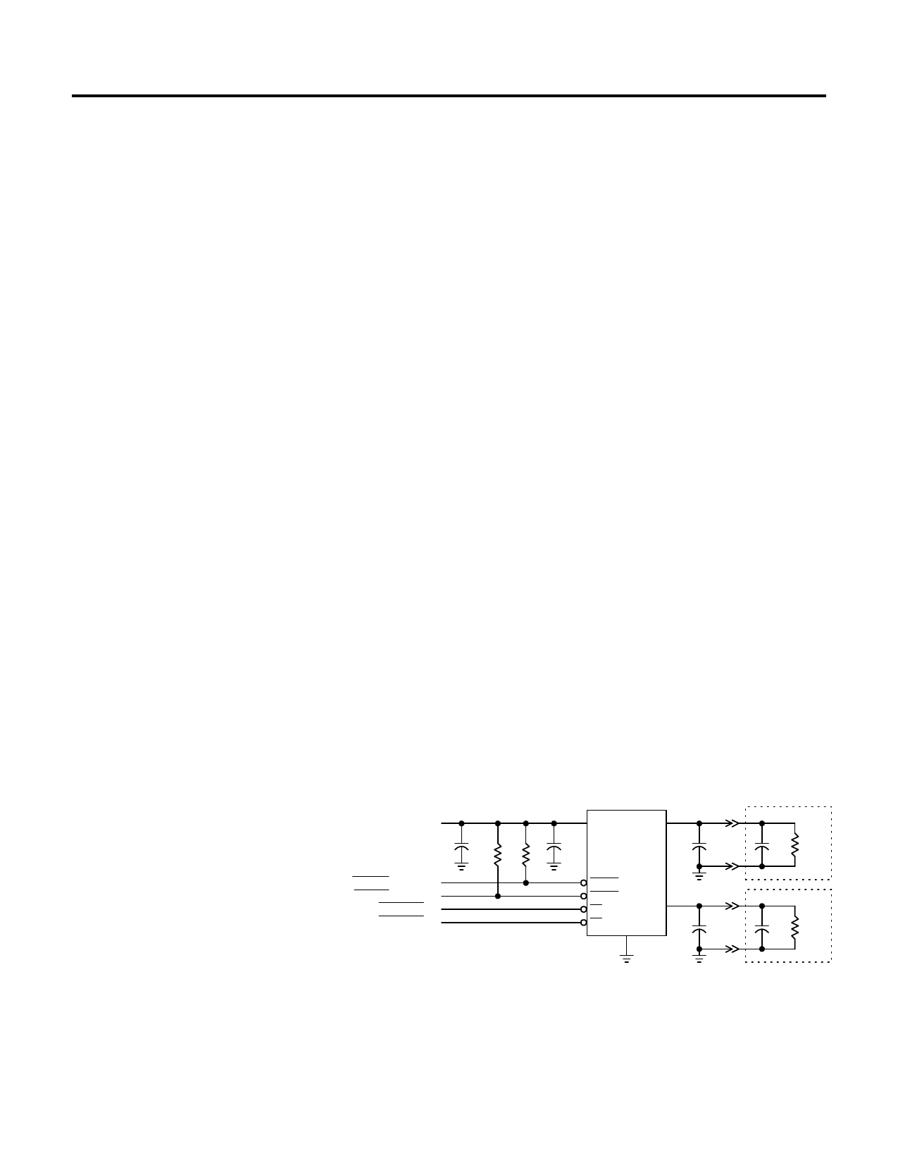
TYPICAL APPLICATIONS
POWER SUPPLY
4.0V - 5.0V
ERROR FLAG A
ERROR FLAG B
ENABLE A
ENABLE B
7
IN
8
OUT A
1µF
0.1µF
10k 10k
2 ERROR A
3
1
ERROR B
EN
OUT B
5
4 EN
GND
6
EXTERNAL LOAD A
0.1µF
EXTERNAL LOAD B
0.1µF
Figure 1
Advanced Monolithic Systems, Inc. 6680B Sierra Lane, Dublin, CA 94568 Phone (925) 556-9090 Fax (925) 556-9140
Share Link: 