PBL38813 Просмотр технического описания (PDF) - Ericsson
Номер в каталоге
Компоненты Описание
Список матч
PBL38813 Datasheet PDF : 16 Pages
| |||
PBL 388 13
Loudspeaker amplifier
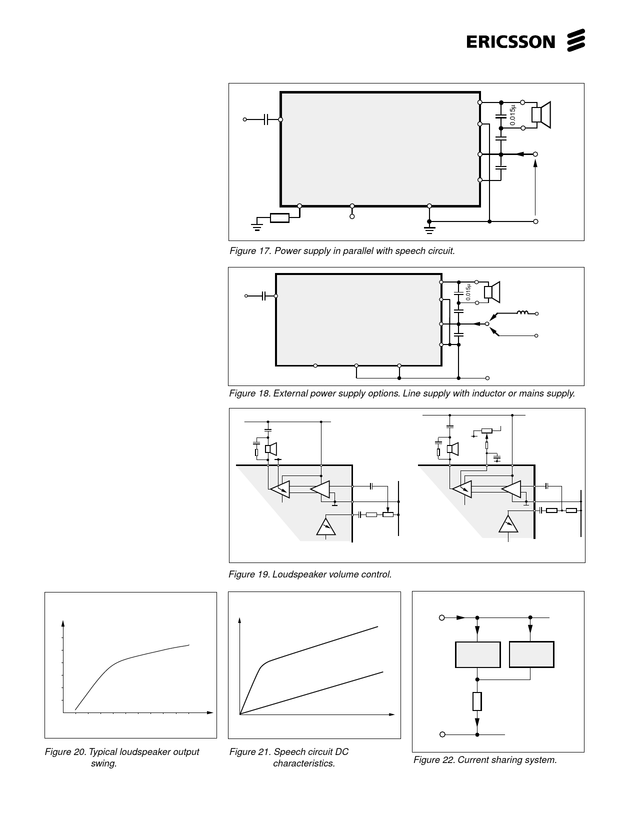
The loudspeaker amplifier drives
directly a 25 - 50Ω impedance loudspeaker.
The amplifier is designed to work under a
number of different power supply conditions.
Fig. 17, 18 and 23. The highest output
swing is obtained if pin -C is connected to
ground (- Line) and pin +L is connected to
a stable DC supply. This supply could be
either mains powered or powered from the
telephone line through an inductor. Fig.18.
Current consumption is directly proportio-
nal to the voltage between pins +L and -C.
When using the application according to
figure 17, pin -C is used as the negative
floating supply point for the amplifier. The
output signal of the loudspeaker amplifier
is referred to +L. The reservoir capacitor C
makes it possible for the amplifier to handle
power peaks that are much higher than
would be possible with continuous signal.
The optimal design without using a stable
supply is to balance it against the DC char-
acteristics of the speech circuit that is
working in parallel. This is the main reason
why the power stage is referred to the +line
because otherways there would be the
resistor to ground (-line), see fig. 22. Such
an arrangement is known to be extremely
troublesome in respect of RFI (Radio
Frequency Interference). The single ended
loudspeaker amplifier has an internal gain
regulation that prevents distortion in case
of insufficient line current. The loudspeaker
volume control can be solved in two diffe-
rent ways. One is to use a conventional
potentiometer that will act as an ac voltage
divider at the power amplifier input pin 23.
The second is to control the gain of the
power amplifier by dc. at pin 19. See fig.19.
The controlling element can be a potentio-
meter or a digital control from a µ-proces-
sor. See figure 24.
Input
0.22 µ
23 LSP in
PBL 388 13
LSP 18
VOL 19
+L 20
RE
R DC
22
21
–C 17
GND
16
RE
Connected to speech circuit
pin 2. (see figure 23.)
Figure 17. Power supply in parallel with speech circuit.
50 ohm
100 µF
+ 16V
+ I+L
+ Line
1000 µF
16V
VLine
– Line
Input
0.22 µ
23 LSPin
PBL 388 13
LSP 18
VOL 19
+L 20
–C 17
RE
R DC
GND
22
21
16
50 ohm
100 µF 1
+ 16V
+ Line
(Alt.1 and 2)
+ I+L
2
1000 µF
16V
Regulated voltage
from
mains supply
– Line
Figure 18. External power supply options. Line supply with inductor or mains supply.
+line
+
50 Ω LOUD
SPEAKER
0V
18 19
20
23
16
PBL 388 13
11
F6
AC-control
+line
+
+
0V
50 Ω LOUD
SPEAKER
0V
18
19
20
23
0V
16
PBL 388 13
11
F6
0V
DC-control
Figure 19. Loudspeaker volume control.
V
V0ut (Vp)
2.4
2.0
1.6
1.2
0.8
0.4
0
20
40
60
ILine
(mA)
80
100
V +Line
VRDC
I Line
+Line I L
IB
Speech
Circuit
Z≈0
R
-Line
IR
IC
Handsfree
Circuit
Figure 20. Typical loudspeaker output
swing.
Figure 21. Speech circuit DC
characteristics.
Figure 22. Current sharing system.
10
Share Link: 