SL34118 Просмотр технического описания (PDF) - System Logic Semiconductor
Номер в каталоге
Компоненты Описание
Список матч
SL34118 Datasheet PDF : 12 Pages
| |||
SL34118
ATTENUATOR CONTROL BLOCK
The Attenuator Control Block has the seven
inputs described above:
- Tthe output of the comparator operated by RLO2
and TLO2 (microphone/speaker side) - designated
C1.
- The output of the comparator operated by RLO1
and TLO1 (Tip/Ring) side) - designated C2.
- The output of the transmit background noise
monitor - designated C3.
- The output of the receive background noise
monitor - designated C4.
- The volume control.
- The dial tone detector.
- The AGC circuit.
The single output of the Control Block controls
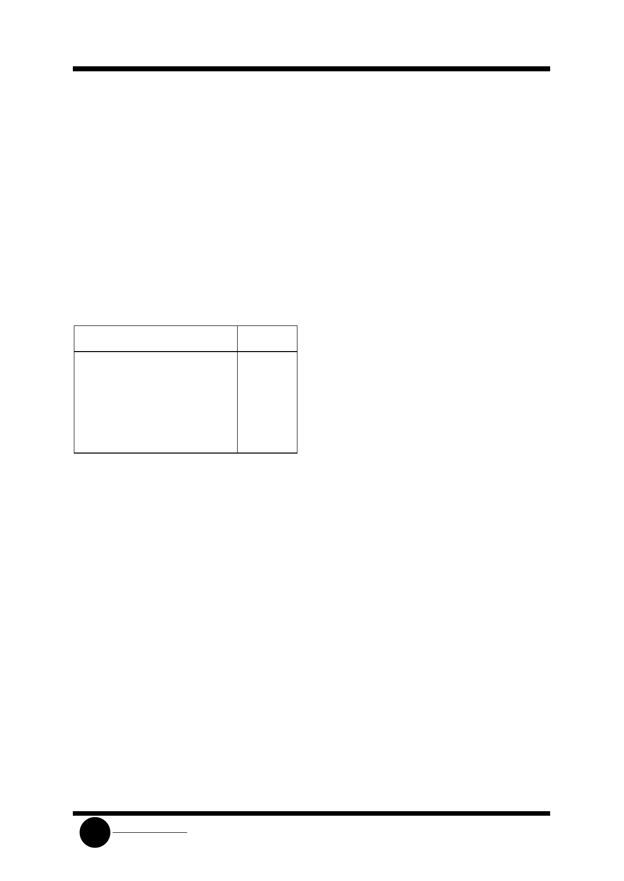
the two attenuators. The effect of C1-C4 is as follows:
Inputs
Output
C1
C2
C3
C4
Mode
Tx
Tx
1
X
Transmit
Tx
Rx
Y
Y
Fast Idle
Rx
Tx
Y
Y
Fast Idle
Rx
Rx
X
1
Receive
Tx
Tx
0
X
Slow Idle
Tx
Rx
0
0
Slow Idle
Rx
Tx
0
0
Slow Idle
Rx
Rx
X
0
Slow Idle
X = Don’t Care; Y = C3 and C4 are not both 0
A definition of the above terms:
1) “Transmit” means the transmit attenuator is
fully on (+6.0 dB), and the receive attenuator is
at max. attenuation (-46 dB).
2) “Receive” means both attenuators are
controlled by the volume control. At max.
volume, the receive attenuator is fully on
(6.0 dB), and the transmit attenuator is at max.
attenuation (-46 dB).
3) “Fast Idle” means both transmit and receive
speech are present in approximately equal levels.
The attenuators are quickly switched (30 ms) to
idle until one speech level dominates the other.
4) “Slow Idle” means speech has ceassed in both
transmit and receive path. The attenuators are
then slowly switched (1 second) to the idle
mode.
5) Switching to the full transmit or receive modes
from any other mode is at the fast rate (30 ms).
A summary of the truth table is as follows:
1) The circuit will switch to transmit if: a) both
transmit level detectors sense higher signal levels
relative to the respective receive level detectors (TLI1
versus RLI1, TLI2 versus RLI2), and b) the transmit
background noise monitor indicates the presence of
speech.
2) The circuit will switch to receive if: a) both
receive level detectors sense higher signal levels
relative to the respective transmit level detectors, and
b) the receive background noise monitor indicates the
presence of speech.
3) The circuit will switch to the fast idle mode if the
level detectors disagree on the relative strengths of
the signal levels, and at least one of the background
noise monitors indicates speech. For example,
refferring to the Expanded Logic Diagram (Figure 8), if
there is sufficient signal at the microphone amp
output (TLI2) to override the speaker signal (RLI2),
and there is sufficient signal at the receive input
(RLI1) to override the signal at the hybrid output
(TLI1), and either or both background monitors
indicate speech, then the circuit will be in the fast idle
mode. Two conditions which can cause the fast idle
mode to occur are a) when both talkers are attempting
to gain control of the system by talking at the same
time, and b) when one talker is in a very noisy
environment, forcing the other talker to continually
override that noise level. In general, the fast idle mode
will occur infrequently.
4) The circuit will switch to the slow idle mode
when a) both talkers are quiet (no speech present), or
b) when one talker’s speech level is continuously
overriden by noise at the other speaker’s location.
The time required to switch the circuit between
transmit, receive, fast idle and slow idle is determined
in part by the components at the CT pin (Pin 14). A
schematic of the CT circuitry is shown in Figure 4 and
operates as follows:
- RT is typically 120 kΩ, and CT typically 5.0 µF.
- To switch to the receive mode, I1 is turned on (I2 is
off), charging the external capacitor to +240 mV
above VB. (An internal clamp prevents further
charging of the capacitor.)
- To switch to the transmit mode, I2 is turned on (I1
is off) bringing down the voltage on the capacitor
to -240 mV with respect to VB.
- To switch to idle quickly (fast idle), the current
sources are turned off, and the internal 2.0 kΩ
resistor is switched in, discharging the capacitor
to VB with a time constant = 2.0 KΩ x CT.
- To switch to idle slowly (slow idle), the current
sources are turned off, the switch at the 2.0 kΩ
resistor is open, and the capacitor discharges to
VB through the external resistor RT with a time
constant = RT x CT.
SLS
System Logic
Semiconductor
Share Link: 