M52347FP Просмотр технического описания (PDF) - MITSUBISHI ELECTRIC
Номер в каталоге
Компоненты Описание
Список матч
M52347FP Datasheet PDF : 13 Pages
| |||
MITSUBISHI ICs (Monitor)
M52347SP/FP
SYNC SIGNAL PROCESSOR
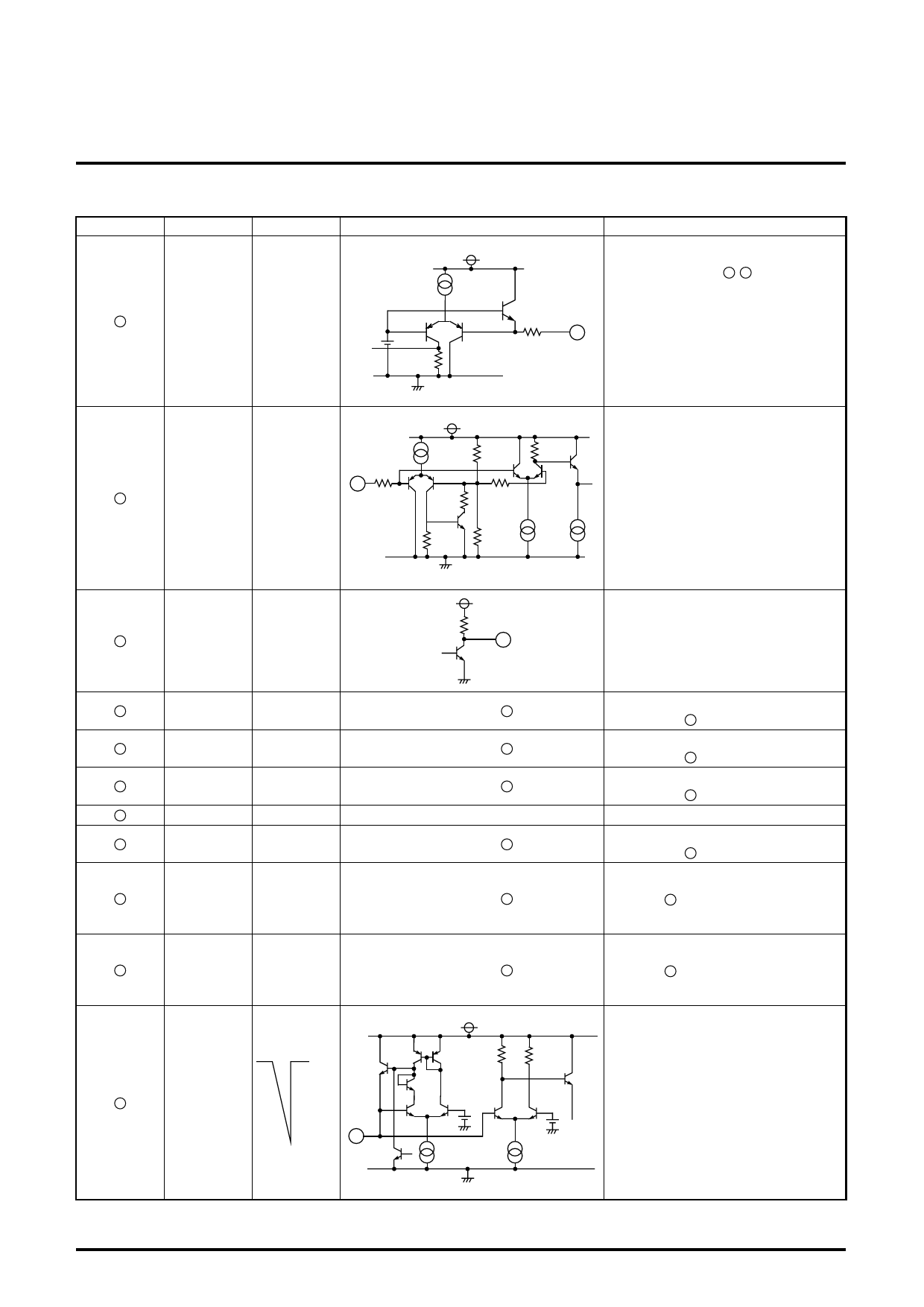
DESCRIPTION OF PIN (cont.)
Pin No.
Name
Pin voltage
V.TEME ≈3.2V when
10
GATE SW open
Peripheral circuit of pins
0.1mA
2.5V
20kΩ
10
30kΩ
Description of function
V TIME GATE SW pin
Can select whether to output the pulse of
VD portion from pin 14 , 15 output pluse.
The threshold voltage is approx. 2.5V.
VTH L=0 to 2V
VTH H=3 to 5V
V S/S
11
IN
0.1mA
7.5kΩ
V S/S IN pin
Inputs a signal of having externally inte-
grated composite sync for V sync separa-
4kΩ
tion.
11
1kΩ
5.5kΩ
20kΩ
1kΩ
1.75kΩ
0.2mA 0.2mA
V S/S
12
OUT
13
VD+OUT
14
HD+OUT
15
HD-OUT
16
VCC
5V
17
CLAMP+
OUT
18
H.POL.
0 VDC or
5 VDC
19
V.POL.
0 VDC or
5 VDC
CLAMP
20
TIMING
3.0V
1.9V 20
1kΩ
12
Same as pin 12
Same as pin 12
Same as pin 12
Same as pin 12
Same as pin 1
Same as pin 1
4kΩ
3V
4kΩ
1.9V
V S/S pulse output pin
No problem occurs when current of
approx. 6 mA flows to internal part of the
IC. To improve the rising speed, connect
a resistance between power supplies.
VD+ pulse output pin
Same as pin 12
HD+ pulse output pin
Same as pin 12
HD- pulse output pin
Same as pin 12
Power supply
CLAMP+ pulse output pin
Same as pin 12
Logic output pin for horizontal synchro-
nous signal
When pin 6 input signal is POSI, outputs
"L"; when NON, outputs "L"; and when
NEG, outputs "H".
Logic output pin for vertical synchronous
signal
When pin 8 input signal is POSI, outputs
"L"; when NON, outputs "L"; and when
NEG, outputs "H".
CLAMP TIMING pin
The clamp pulse width is determined
depending on the external resistance and
capacitance. As the resistance value and
capacitance value are larger, the clamp
pulse width is wider.
0.4mA
0.2mA
8
Share Link: 