M66011FP Просмотр технического описания (PDF) - MITSUBISHI ELECTRIC
Номер в каталоге
Компоненты Описание
Список матч
M66011FP Datasheet PDF : 12 Pages
| |||
MITSUBISHI 〈DIGITAL ASSP〉
M66011FP
SERIAL BUS CONTROLLER
4. Shift clock output
Shift clock output pin (SCLK) outputs clock pulses gener-
ated by ceramic resonator oscillation circuit connected be-
tween pins Xin and Xout, or divided clock pulses input via
pin Xin from external clock. The dividing ratio can be se-
lected from among 1/2, 1/4, 1/8 and 1/16.
5. Interrupt output
When interrupt output control register is set to “1” (inter-
rupt output enable), the status of this output shifts from “L”
to “H” at the end of a serial communication cycle, and an
interrupt command is given to microcomputer. Interrupt
output “H” is reset when read accessed.
When interrupt output control register is set to “0” (inter-
rupt output disable), the status of this output is retained on
the “L” level.
6. Conditions when reset
If “L” is input to RESET, M66011 are put under the condi-
tions as specified below:
Pin name
OE, SCLK and SOUT outputs
Internal busy flag
Acknowledge bit register
INT output
Divider ratio
Status
Active (“H”)
Reset (“L”)
Set (“H”)
Disable (continuous “L” output)
1/2
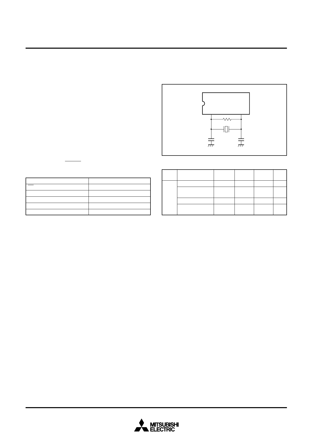
7. Oscillation circuit
An example of circuit connection and circuit constants are
given below for the case where a ceramic resonator is
used.
M66011FP
Xin
Xout
Rf
Ceramic resonator
C1
C2
Clock Oscillation Circuit
Maker
Murata
Mfg.
Ceramic
resonator
Frequency C1
(MHz) (pF)
CSA4.00 MG 040
4.0
100
CST4.00 MGW 040
4.0
100
(built-in)
CSA8.00 MT
8.0
30
CSA8.00 MTW
8.0
30
(built-in)
C2
(pF)
100
100
(built-in)
30
30
(built-in)
Rf
(MΩ)
1.0
1.0
1.0
1.0
6
Share Link: 