M66011FP Просмотр технического описания (PDF) - MITSUBISHI ELECTRIC
Номер в каталоге
Компоненты Описание
Список матч
M66011FP Datasheet PDF : 12 Pages
| |||
MITSUBISHI 〈DIGITAL ASSP〉
M66011FP
SERIAL BUS CONTROLLER
OPERATION
1. Write operation
(1) Serial output data setting
The M66011 has two built-in 8-bit shift registers. They are
used to set serial output data.
When the address setting is (A1, A0) = (0, 1), 8-bit data on
data bus is written on the upper byte serial output shift reg-
ister (SRU). When the address setting is (A1, A0) = (0, 0),
the data is written on the lower byte serial output shift reg-
ister (SRL). In either case, data write starts when WR is on
the “L” level.
(2) Status register setting
When the address setting is (A1, A0) = (1, 1), written data
becomes the setting of status register in M66011. (Refer
to the table below.)
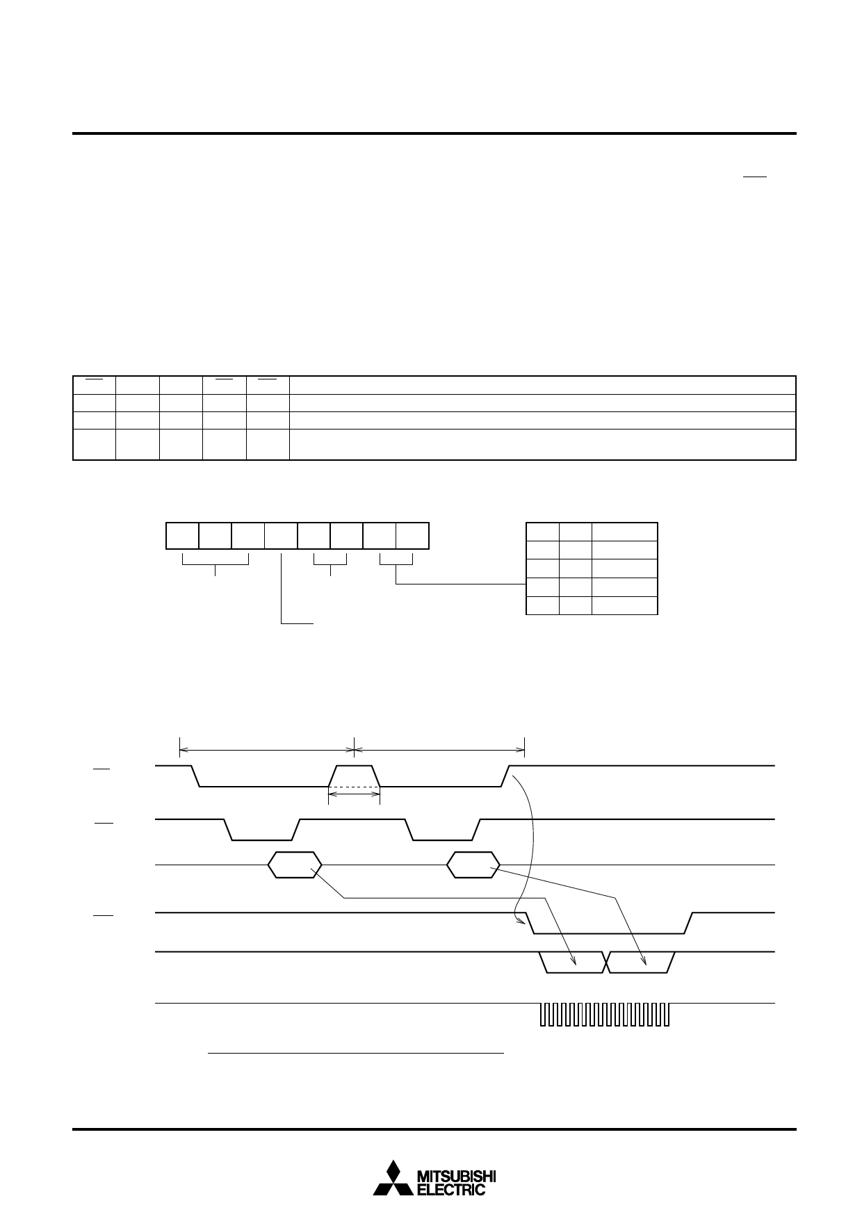
Write Operation Basic Functions (Note 1)
CS A1 A0 RD WR
0
0
0
1
0 • Lower byte serial output shift register
0
0
1
1
0 • Upper byte serial output shift register
0
1
1
1
0
• Shift clock divider ratio register
• Interrupt output control register
Note 1: Figure “0” indicates “L” level, while “1” indicates “H” level.
Functions
←
←
←
Data bus data
Data bus data
(Note 2)
Data bus data
Note 2:
D7 D6 D5
Don’t care
D4 D3 D2 D1 D0
D1 D0 Divider ratio
00
1/2
01
1/4
Don’t care
10
1/8
11
1/16
“0”: Interrupt output disable
(INT output is fixed to “L”.)
“1”: Interrupt output enable
(INT output shifts from “L” to “H” when serial communication is completed.)
CS
WR
Data buses
D0~D7
OE
SOUT
SCLK
Write on SRU
Write on SRL
"L" or "H"
D0U~D7U
D0L~D7L
D7U~D0U D7L~D0L
Write Operation Basic Timing (Serial Output Data Setting)
3
Share Link: 