M74HC652RM13TR Просмотр технического описания (PDF) - STMicroelectronics
Номер в каталоге
Компоненты Описание
Список матч
M74HC652RM13TR Datasheet PDF : 14 Pages
| |||
M74HC652
OCTAL BUS TRANSCEIVER/REGISTER
WITH 3 STATE OUTPUTS
s HIGH SPEED:
fMAX = 79 MHz (TYP.) at VCC = 6V
s LOW POWER DISSIPATION:
ICC = 4µA(MAX.) at TA=25°C
s HIGH NOISE IMMUNITY:
VNIH = VNIL = 28 % VCC (MIN.)
s SYMMETRICAL OUTPUT IMPEDANCE:
|IOH| = IOL = 6mA (MIN)
s BALANCED PROPAGATION DELAYS:
tPLH ≅ tPHL
s WIDE OPERATING VOLTAGE RANGE:
VCC (OPR) = 2V to 6V
s PIN AND FUNCTION COMPATIBLE WITH
74 SERIES 652
DESCRIPTION
The M74HC652 is an advanced high-speed
CMOS OCTAL BUS TRANSCEIVER AND
REGISTER (3-STATE) fabricated with silicon gate
C2MOS technology.
This device consists of bus transceiver circuits,
D-type flip-flops, and control circuitry arranged for
multiplexed transmission of data directly from the
input bus or from the internal storage registers.
Enable GAB and GBA are provided to control the
transceiver functions. Select AB (SAB) and select
BA (SBA) control pins are provided to select
whether real-time or stored data is transferred. A
low input level selects real-time data, and a high
selects stored data.
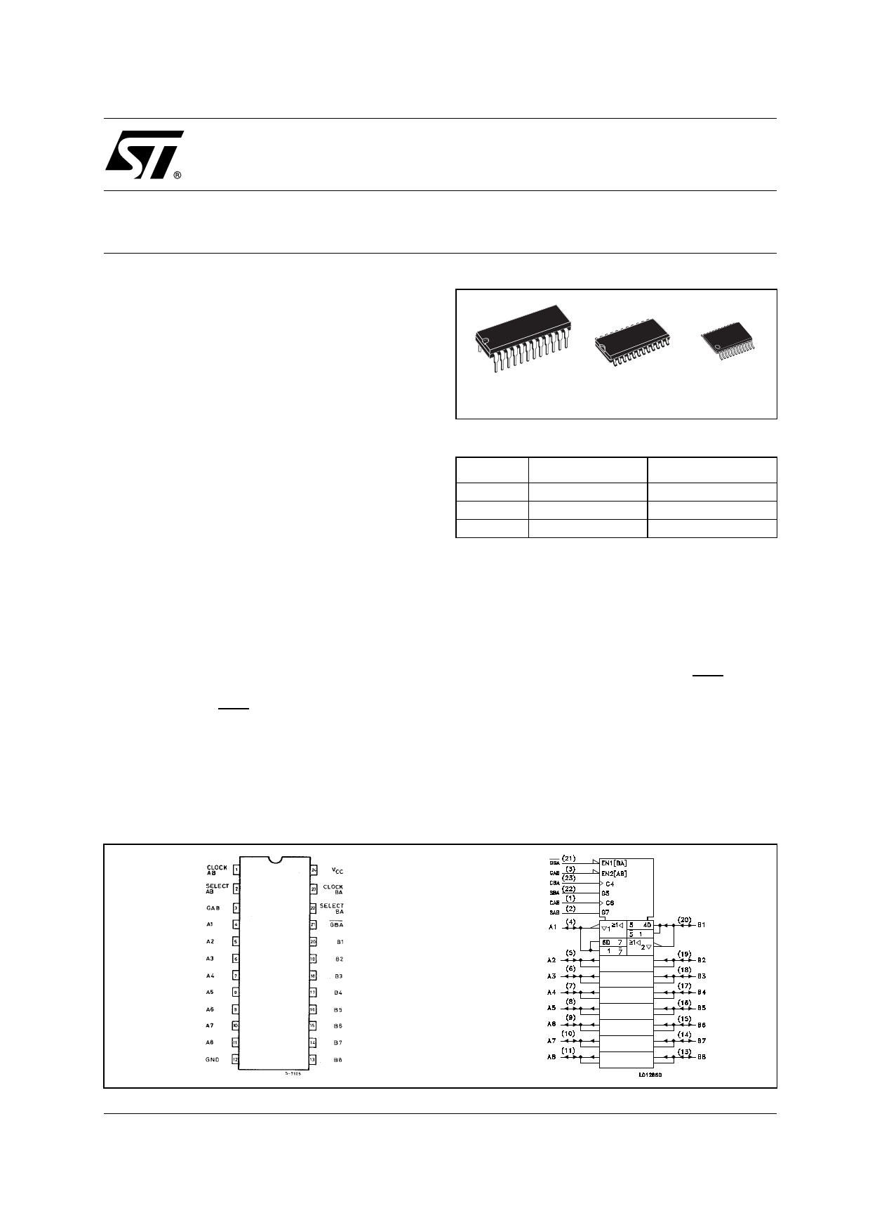
PIN CONNECTION AND IEC LOGIC SYMBOLS
DIP
SOP
TSSOP
ORDER CODES
PACKAGE
TUBE
DIP
SOP
TSSOP
M74HC652B1R
M74HC652M1R
T&R
M74HC652RM13TR
M74HC652TTR
Data on the A or B bus, or both, can be stored in
the internal D flip-flops by low-to-high transition at
the appropriate clock pins (CLOCK AB or CLOCK
BA) regardless of the select or enable control pins.
When select AB and select BA are in the real time
transfer mode, it is also possible to store data
without using the internal D type flip-flops by
simultaneously enabling GAB and GBA. In this
configuration each output reinforces its input.
Thus, when all other data sources to the two sets
of bus lines are at high impedance, each set of
bus lines will remain at its last state.
All inputs are equipped with protection circuits
against static discharge and transient excess
voltage.
August 2001
1/14
Share Link: 