M56785FP Просмотр технического описания (PDF) - MITSUBISHI ELECTRIC
Номер в каталоге
Компоненты Описание
Список матч
M56785FP Datasheet PDF : 11 Pages
| |||
MITSUBISHI <CONTROL / DRIVER IC>
M56785FP
SPINDLE MOTOR DRIVER
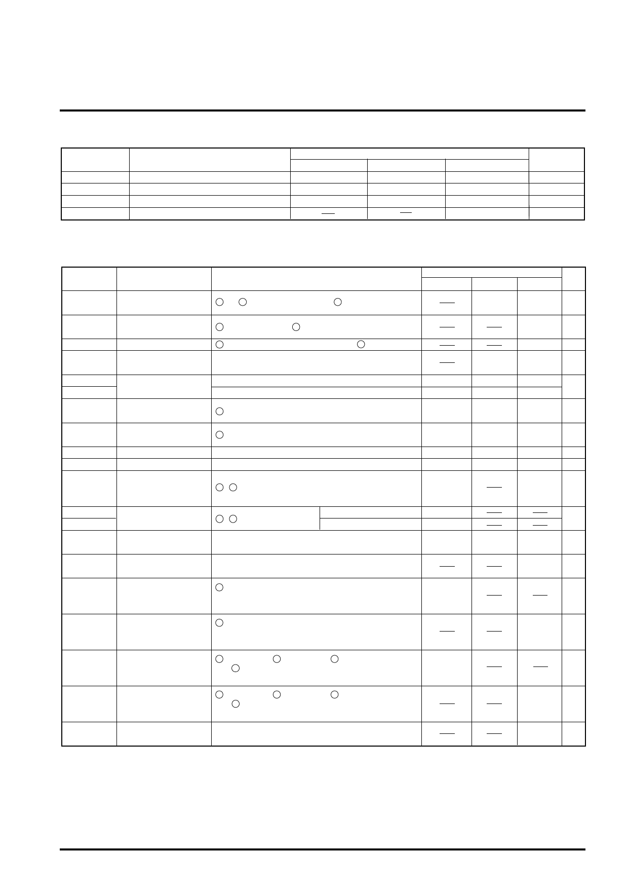
RECOMMENDED OPERATING CONDITIONS
Symbol
Parameter
Min.
VCC1
5V Power supply
4.5
VCC2
12V Power supply
4.5
VM
Motor Power supply
4.5
Io
Output drive current
Limits
Typ.
5.0
12.0
12.0
Max.
Unit
5.5
V
13.2
V
13.2
V
700
mA
ELECTRICAL CHARACTERISTICS (VCC=5V, VCC2=12V, VM=12V, Ta=25˚C unless otherwise noted.)
Symbol
Parameter
Conditions
Min.
Icc1
Sleep Mode Supply
current- 1
15 and 16 pin total Input Current ( 2 pin low or open)
Icc2
Sleep Mode Supply
current- 2
19 pin Input Current ( 2 pin low or open)
Icc3
Supply current- 3
19 pin Input Current (EC=ECR=2.5V) [ 2 pin High]
Vsat
Saturation voltage
Top and Bottom saturation voltage.
(Load current :500mA)
ECdead- Dead Zone Control
EC < ECR
-40
ECdead+ voltage dead zone
EC > ECR
0
ECR
Reference voltage
Input range
18 pin [3.3v DSP available]
0.5
EC
Control voltage Input
range
17 pin [3.3v DSP available]
0.5
Gio
Control gain
Io = Gio / Rsense [A/V]
0.25
Vlim
Control limit
Ilim = Vlim / Rsense [A]
0.27
Hall sensor amp
VH com
common mode input 23 – 28 pins
1.2
range
VHmin1
VHmin2
Hall sensor amp.
input signal revel
23 – 28 pins
MODE4=OPEN or HIGH
50
MODE4=GND
35
VHb
Hall bias terminal
output voltage
Load current (IHb) =10 mA.
0.6
IHb
Hall bias terminal sink
current
Limits
Typ.
0
1.2
-21
+21
1.65
1.65
0.3
0.3
0.85
Max. Unit
100
µA
500
µA
6.0 mA
1.9
V
0
mV
+40
4.0
V
4.0
V
0.35 V/V
0.33
V
4.5
V
mV
p-p
1.2
V
30
mA
2 pin input voltage when it starts up the motor.
Von
Motor start voltage
*The IC is in the active condition.
2.0
V
*The hall bias is available.
2 pin input voltage when it stops the motor.
Voff
Motor stop voltage
*The IC is in the sleep condition.
*The hall bias is off.
0.8
V
ViH
mode pin input high
voltage
7 pin[MODE1], 6 pin[MODE2], 37 pin[MODE3]
and 36 pin[MODE4] input voltage
when they are HIGH.
2.0
V
mode pin input low
7 pin[MODE1], 6 pin[MODE2], 37 pin[MODE3]
ViL
voltage
and 36 pin[MODE4] input voltage
when they are LOW.
0.8
V
VOL
3pin[RDS],4pin[FG]
output low voltage
Io current = 1mA
0.5
V
Share Link: 