AM1744K Просмотр технического описания (PDF) - Matsushita Electric Works
Номер в каталоге
Компоненты Описание
Список матч
AM1744K Datasheet PDF : 9 Pages
| |||
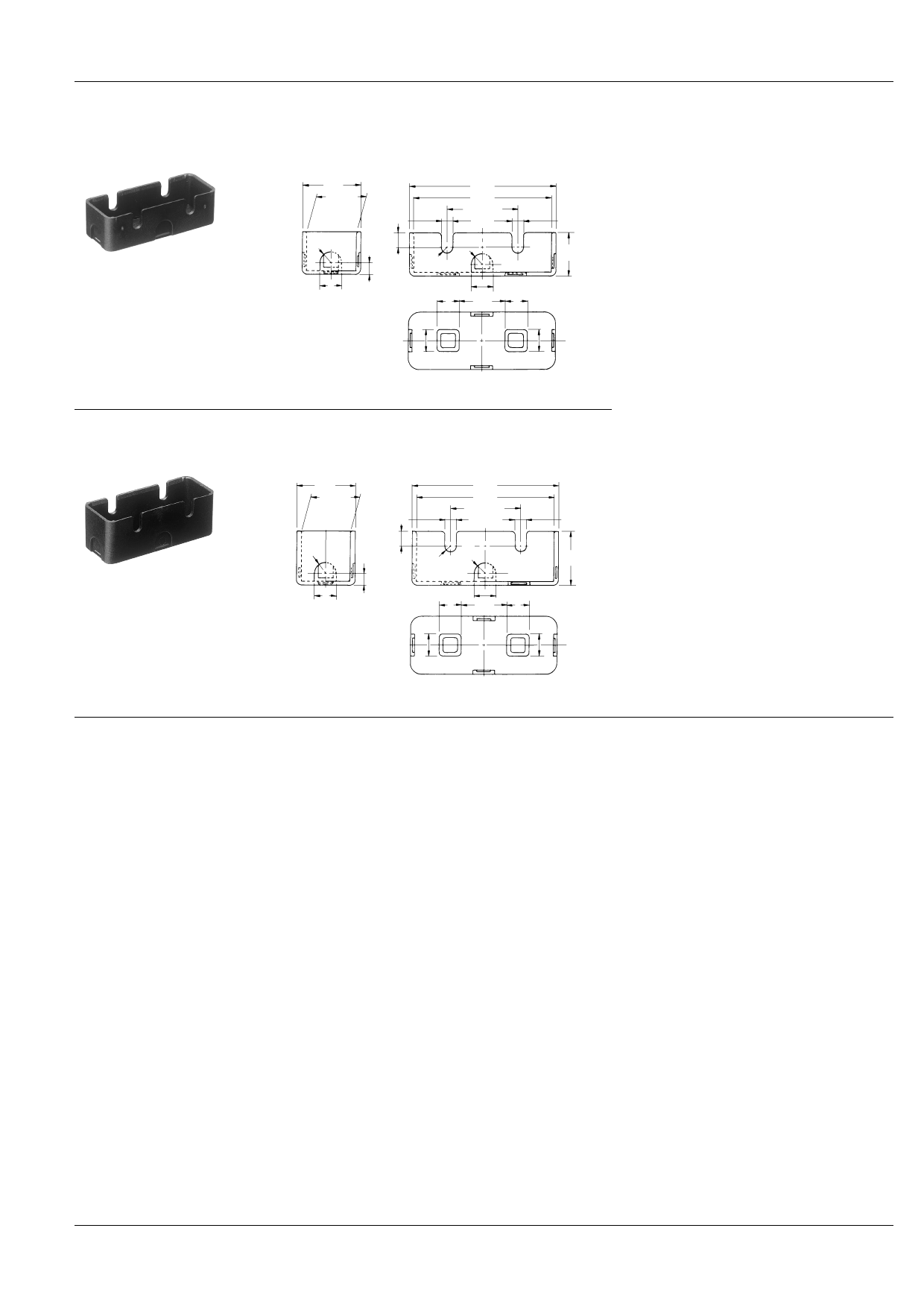
TERMINAL COVER FOR NZ BASIC SWITCHES
Terminal cover
(for the standard type with soldering terminal)
AA7000
21.2
.835
17.9
+0.2
0
.705
+.008
0
4.2
+0.1
−0.05
.165
+.004
−.002
53.2
2.094
50
1.969
25.4±0.1
1.000±.004
R4
.157
5.5 R2.1
.217 .157
R4
.157
8
4.4
.315 .173
8
.315
8 16.5 8
.315 .650 .315
4.2
+0.1
−0.05
.165 +−..000042
16
.630
8
8
.315
.315
Terminal cover
(for the standard type with screw terminal)
AA8000
21.2
.835
17.9+00.2
.705+.0008
4.2
+0.1
−0.05
.165
+.004
−.002
53.2
2.094
50
1.969
25.4±0.1
1.000±.004
R4
.157
8
.315
4.4
.173
R4
5.5
.217
R2.1 .157
.157
8
8
16.5 .3158
.315 .650 .315
4.2
+0.1
−0.05
.165 +−..000042
20
.787
AM1
mm inch General tolerance: ±0.4 ±.016
1. Terminal cover can protect switches from ex-
ternal force and the leakage between termi-
nals can be avoided. Also it can be a simple
safety protector because the direct touch of
fingers to terminals can be avoided.
2. Nylon 66 is used for higher durability.
3. The height of terminal cover for the solder
types is lower than terminal cover for the
screw types.
4. AA7000 and AA8000 have 6 knoch-out por-
tions. Lead wire can be taken out from any
desired portion.
8
8
.315
.315
NOTES
1. Regarding fastening of switch body
1) In fastening the switch body, use M4
mounting screws to attach switches with
the torque 1.5 N·m {15 kg·cm} or less.
2) After mounting and wiring, the insula-
tion distance between ground and each
terminal should be confirmed as suffi-
cient.
2. Adjustment of the operating device
The operating device should be posi-
tioned so that it applies no stress to the
pushbutton or actuator when the switch is
in the open position. If this condition is ex-
ceeded, the mechanical and electrical
performance will be impaired. In addition,
the force applied by the operating device
should be in a perpendicular direction.
Even if the pushbutton is used in the full
total travel position, there will be no influ-
ence on the life of the switch.
3. Soldering operations
Soldering should be done in less than 5
seconds, with a 60 watt iron (tip tempera-
ture = 350°C 662°F max.). Care should be
taken not to apply force to the terminal
during soldering.
4. Avoid using switches in the follow-
ing conditions:
• In corrosive gases such as hydrogen sul-
fide.
• In flammable or explosive gases such as
gasoline or thinner etc.
• In a dusty environment.
• In an ambient humidity over 85%.
• In the conditions where the perpendicu-
lar operating speed is less than 0.1 mm/
sec. or more than 1,000 mm/sec.
• In a silicon atmosphere.
5. Others
Caution should be taken not to drop
switches.
51
Share Link: 