HMC256 Просмотр технического описания (PDF) - Micross Components
Номер в каталоге
Компоненты Описание
Список матч
HMC256 Datasheet PDF : 9 Pages
| |||
v03.1007
HMC256
GaAs MMIC I/Q MIXER
5.9 - 12 GHz
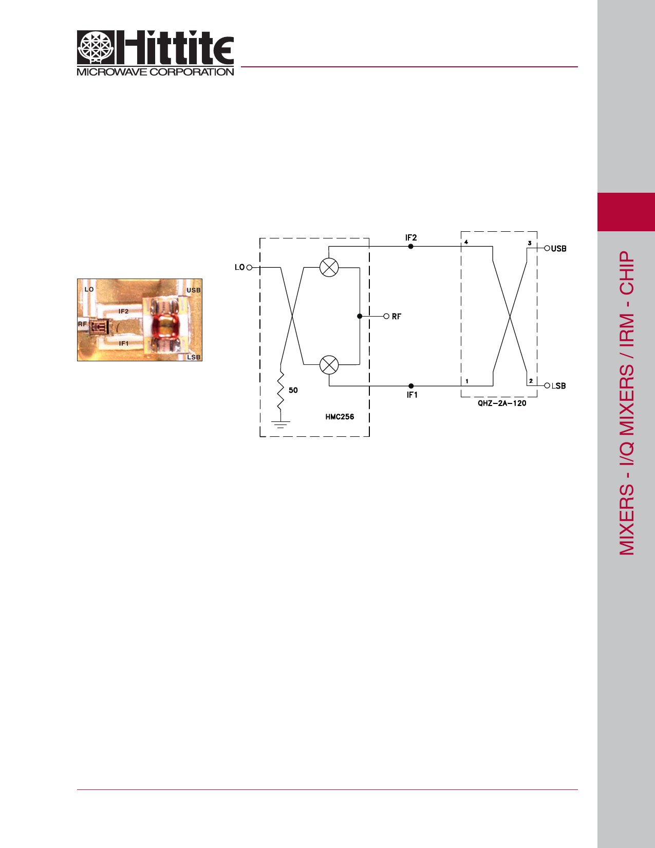
Image Reject Mixer Suggested Application Circuit
Below in Figure 1 is a photo and in Figure 2 a schematic of the HMC256 image reject mixer MMIC die connected to a quadrature
hybrid (120 MHz) manufactured by Merrimac Industries West Caldwell, NJ (P/N QHZ-2A-120).
Data presented for the HMC256 MMIC IRM was obtained using the circuit described here. Please note that the image rejection
and isolation performance is dependent on the selection of the low frequency hybrid. The performance specification of the low
frequency quadrature hybrid as well as the phase balance and VSWR of the interface circuit to the HMC256 MMIC will effect the
overall IRM performance.
3
Figure 1:
Complete MIC IRM Assembly
Handling Precautions
Figure 2:
Schematic of HMC256 IRM MMIC
Connected to the Quadrature Hybrid
Follow these precautions to avoid permanent damage.
Storage: All bare die are placed in either Waffle or Gel based ESD protective containers, and then sealed in an ESD protective bag
for shipment. Once the sealed ESD protective bag has been opened, all die should be stored in a dry nitrogen environment.
Cleanliness: Handle the chips in a clean environment. DO NOT attempt to clean the chip using liquid cleaning systems.
Static Sensitivity: Follow ESD precautions to protect against ESD strikes.
Transients: Suppress instrument and bias supply transients while bias is applied. Use shielded signal and bias cables to minimize
inductive pick-up.
General Handling: Handle the chip along the edges with a vacuum collet or with a sharp pair of bent tweezers. The surface of the
chip has fragile air bridges and should not be touched with vacuum collet, tweezers, or fingers.
Mounting
The chip is back-metallized and can be die mounted with AuSn eutectic preforms or with electrically conductive epoxy. The mounting
surface should be clean and flat.
Eutectic Die Attach: A 80/20 gold tin preform is recommended with a work surface temperature of 255 °C and a tool temperature
of 265 °C. When hot 90/10 nitrogen/hydrogen gas is applied, tool tip temperature should be 290 °C. DO NOT expose the chip
to a temperature greater than 320 °C for more than 20 seconds. No more than 3 seconds of scrubbing should be required for
attachment.
Epoxy Die Attach: Apply a minimum amount of epoxy to the mounting surface so that a thin epoxy fillet is observed around the
perimeter of the chip once it is placed into position. Cure epoxy per the manufacturer’s schedule.
Wire Bonding
Ball or wedge bond with 0.025 mm (1 mil) diameter pure gold wire. Thermosonic wirebonding with a nominal stage temperature of
150 °C and a ball bonding force of 40 to 50 grams or wedge bonding force of 18 to 22 grams is recommended. Use the minimum
level of ultrasonic energy to achieve reliable wirebonds. Wirebonds should be started on the chip and terminated on the package or
substrate. All bonds should be as short as possible <0.31 mm (12 mils).
For price, delivery, and to place orders, please contact Hittite Microwave Corporation:
20 Alpha Road, Chelmsford, MA 01824 Phone: 978-250-3343 Fax: 978-250-3373
Order On-line at www.hittite.com
3-7
Share Link: 