PS9117 Просмотр технического описания (PDF) - California Eastern Laboratories.
Номер в каталоге
Компоненты Описание
Список матч
PS9117
California Eastern Laboratories.

PS9117 Datasheet PDF : 10 Pages
| |||
PS9117
*1 Typical values at TA = 25°C
*2 Because VOL of 2 V or more may be output when LED current input and when output supply of VCC = 2.6 V or less, it is
important to confirm the characteristics (operation with the power supply on and off) during design, before using this device.
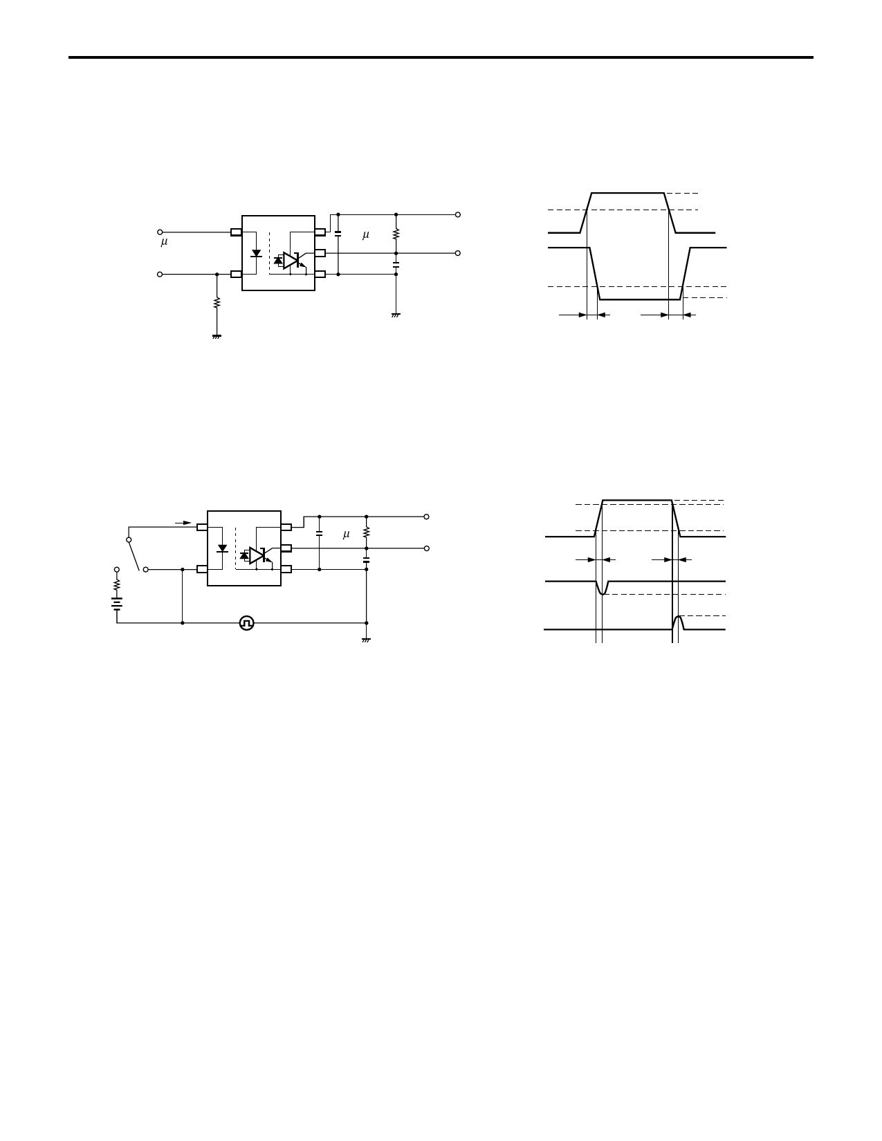
*3 Test circuit for propagation delay time
Pulse input (IF)
(PW = 1 µs,
Duty cycle = 1/10)
Input
(monitor)
47 Ω
0.1 µ F
VCC = 5 V
RL = 350 Ω
VO (monitor)
CL = 15 pF
Input
Output
tPHL
(IF = 7.5 mA)
50%
1.5 V
tPLH
VOL
Remark CL includes probe and stray wiring capacitance.
*4 Test circuit for common mode transient immunity
SW
IF
VCC = 5 V
VCM 90%
0.1 µF RL = 350 Ω
10%
VO (monitor)
CL = 15 pF
tr
tf
VO
(IF = 0 mA)
VCM
VO
(IF = 7.5 mA)
Remark CL includes probe and stray wiring capacitance.
1 kV
0V
VOH
2V
0.8 V
VOL
USAGE CAUTIONS
1. This product is weak for static electricity by designed with high-speed integrated circuit so protect against static electricity
when handling.
2. By-pass capacitor of 0.1 μF is used between VCC and GND near device. Also, ensure that the distance between the leads of
the photocoupler and capacitor is no more than 10 mm.
Share Link: