MCR100 Просмотр технического описания (PDF) - Kersemi Electronic Co., Ltd.
Номер в каталоге
Компоненты Описание
Список матч
MCR100 Datasheet PDF : 6 Pages
| |||
MCR100 Series
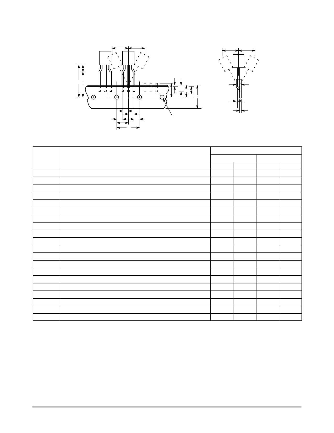
TO−92 EIA RADIAL TAPE IN FAN FOLD BOX OR ON REEL
H2A
H2A
H2B
H2B
H
H4 H5
W2
T1
L1 H1
W1 W
L
T
F1
T2
F2
P2
P2
D
P1
P
Figure 7. Device Positioning on Tape
Specification
Inches
Millimeter
Symbol
Item
Min
Max
Min
Max
D
Tape Feedhole Diameter
0.1496
0.1653
3.8
4.2
D2
Component Lead Thickness Dimension
0.015
0.020
0.38
0.51
F1, F2 Component Lead Pitch
0.0945
0.110
2.4
2.8
H
Bottom of Component to Seating Plane
.059
.156
1.5
4.0
H1
Feedhole Location
0.3346
0.3741
8.5
9.5
H2A
Deflection Left or Right
0
0.039
0
1.0
H2B
Deflection Front or Rear
0
0.051
0
1.0
H4
Feedhole to Bottom of Component
0.7086
0.768
18
19.5
H5
Feedhole to Seating Plane
0.610
0.649
15.5
16.5
L
Defective Unit Clipped Dimension
0.3346
0.433
8.5
11
L1
Lead Wire Enclosure
0.09842
—
2.5
—
P
Feedhole Pitch
0.4921
0.5079
12.5
12.9
P1
Feedhole Center to Center Lead
0.2342
0.2658
5.95
6.75
P2
First Lead Spacing Dimension
0.1397
0.1556
3.55
3.95
T
Adhesive Tape Thickness
0.06
0.08
0.15
0.20
T1
Overall Taped Package Thickness
—
0.0567
—
1.44
T2
Carrier Strip Thickness
0.014
0.027
0.35
0.65
W
Carrier Strip Width
0.6889
0.7481
17.5
19
W1
Adhesive Tape Width
0.2165
0.2841
5.5
6.3
W2
Adhesive Tape Position
.0059
0.01968
.15
0.5
NOTES:
1. Maximum alignment deviation between leads not to be greater than 0.2 mm.
2. Defective components shall be clipped from the carrier tape such that the remaining protrusion (L) does not exceed a maximum of 11 mm.
3. Component lead to tape adhesion must meet the pull test requirements.
4. Maximum non−cumulative variation between tape feed holes shall not exceed 1 mm in 20 pitches.
5. Holddown tape not to extend beyond the edge(s) of carrier tape and there shall be no exposure of adhesive.
6. No more than 1 consecutive missing component is permitted.
7. A tape trailer and leader, having at least three feed holes is required before the first and after the last component.
8. Splices will not interfere with the sprocket feed holes.
www.kersemi.com
4
Share Link: 