MC10159P Просмотр технического описания (PDF) - Motorola => Freescale
Номер в каталоге
Компоненты Описание
Список матч
MC10159P Datasheet PDF : 4 Pages
| |||
MC10159
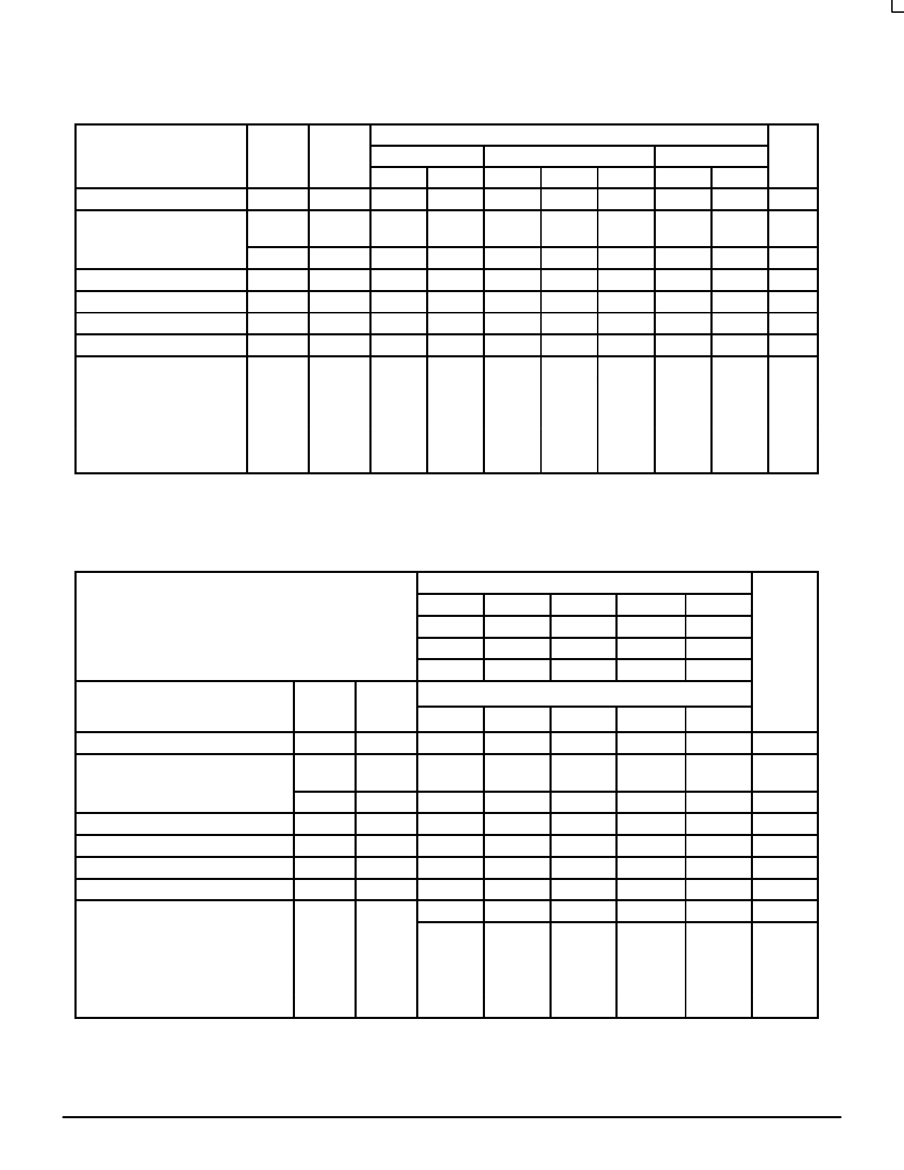
ELECTRICAL CHARACTERISTICS
Characteristic
Power Supply Drain Current
Input Current
Symbol
IE
IinH
Output Voltage
Logic 1
Output Voltage
Logic 0
Threshold Voltage Logic 1
Threshold Voltage Logic 0
Switching Times (50Ω Load)
Propagation
Delay
Data Input
Select Input
Enable Input
Rise Time
(20 to 80%)
Fall Time
(20 to 80%)
IinL
VOH
VOL
VOHA
VOLA
t5+1–
t9+1–
t7+1–
t1+
t1–
Pin
Under
Test
8
9
5
5
1
1
1
1
1
1
1
1
1
–30°C
Min
Max
58
360
400
0.5
–1.060 –0.890
–1.890 –1.675
–1.080
–1.655
1.1
3.8
1.5
5.3
1.4
5.3
1.0
3.7
1.0
3.7
Test Limits
+25°C
Min
Typ
Max
42
53
225
250
0.5
–0.960
–0.810
–1.850
–1.650
–0.980
–1.630
1.2
2.5
3.3
1.5
3.2
5.0
1.5
2.5
5.0
1.1
2.5
3.5
1.1
2.5
3.5
+85°C
Min
Max
58
225
250
0.3
–0.890 –0.700
–1.825 –1.615
–0.910
–1.595
1.1
3.8
1.5
5.3
1.4
5.3
1.0
3.7
1.0
3.7
Unit
mAdc
µAdc
µAdc
Vdc
Vdc
Vdc
Vdc
ns
ELECTRICAL CHARACTERISTICS (continued)
TEST VOLTAGE VALUES (Volts)
@ Test Temperature
–30°C
+25°C
+85°C
VIHmax
–0.890
–0.810
–0.700
VILmin
–1.890
–1.850
–1.825
VIHAmin
–1.205
–1.105
–1.035
VILAmax
–1.500
–1.475
–1.440
VEE
–5.2
–5.2
–5.2
Characteristic
Power Supply Drain Current
Input Current
Symbol
IE
IinH
Pin
Under
Test
8
9
5
TEST VOLTAGE APPLIED TO PINS LISTED BELOW
VIHmax VILmin VIHAmin VILAmax
9
5
VEE
8
8
8
(VCC)
Gnd
16
16
16
Output Voltage
Output Voltage
Threshold Voltage
Threshold Voltage
Switching Times
IinL
5
5
8
16
Logic 1 VOH
1
8
16
Logic 0 VOL
1
5
8
16
Logic 1 VOHA
1
9
6
8
16
Logic 0 VOLA
1
9
6
8
16
(50Ω Load)
+1.11V +0.31V Pulse In Pulse Out –3.2 V
+2.0 V
Propagation Delay
Data Input t5+1–
1
Select Input t9+1–
1
Enable Input t7+1–
1
Rise Time
(20 to 80%)
t1+
1
Fall Time
(20 to 80%)
t1–
1
6
3, 12
9
9
5
1
8
16
9
1
8
16
7
1
5
1
8
16
5
1
8
16
Each MECL 10,000 series circuit has been designed to meet the dc specifications shown in the test table, after thermal equilibrium has been
established. The circuit is in a test socket or mounted on a printed circuit board and transverse air flow greater than 500 linear fpm is maintained.
Outputs are terminated through a 50–ohm resistor to –2.0 volts. Test procedures are shown for only one gate. The other gates are tested in the
same manner.
MOTOROLA
3–66
MECL Data
DL122 — Rev 6
Share Link: 