LD3500 Просмотр технического описания (PDF) - PerkinElmer Inc
Номер в каталоге
Компоненты Описание
Список матч
LD3500 Datasheet PDF : 8 Pages
| |||
Digital Linescan Camera
Data and Power
Connectors (cont.)
Parallel LVDS (RS-644) Models:
The communications connector on the
LD3500 is a MDR36 (mini-D-shell)
connector. This 36 pin connector
provides all communications and
controls needed for camera operation.
Power is provided to the LD3500 via a 6
pin, Hirose HR10A circular jack.
Refer to Table 1b for pinout of the
communications and control connector.
Figure 2 provides pinout locations for
this connector
Camera Construction
The camera head is housed in a rugged,
one piece deep drawn aluminum case,
measuring 2.5" H x 2.5" W x 3.2" L
(excluding lens mounts or connector
extensions) specifically designed for
industrial applications. The sensor is
mounted on an aluminum plate that
efficiently transfers heat to the camera
case. The camera is provided with a
standard 1/4"-20 UNC tripod mounting
block, which can be attached to any of the
four sides of the camera. The mounting
holes used to attach the tripod block can
also be used to mount the camera
assembly. Additionally, the CCD sensor is
thermally coupled to the faceplate of the
camera, and the conductive cooling of this
surface is useful in minimizing thermally
generated dark current and noise of the
camera system.
Optical Interface
The LD3500-series cameras are equipped
with a U-Mount lens interface (MA2-1-
6H) that is aligned to the CCD sensor.
These standard adapters allow the user to
select the optimum lens to suit their
particular application.
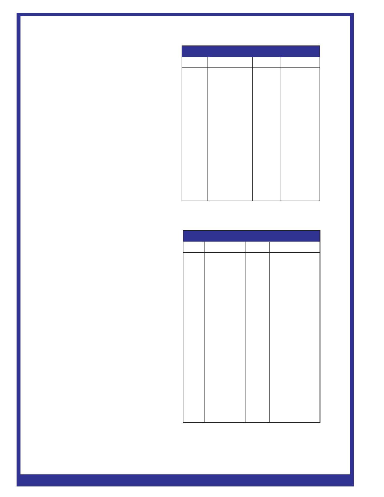
Table 1a. Camera Link Connector Pinout
Pin
Signal
1
Inner Shield
2
X0-
3
X1-
4
X2-
5
Xclk-
6
X3-
7
SerTC+
8
SerTFG-
9
CC1-
10
CC2+
11
CC3-
12
CC4+
13
Inner Shield
Pin
Signal
14
Inner Shield
15
X0+
16
X1+
17
X2+
18
Xclk+
19
X3+
20
SerTC-
21
SerTFG+
22
CC1+
23
CC2-
24
CC3+
25
CC4-
26
Inner Shield
Table 1b. Parallel LVDS (RS-644) Connector Pinout
Pin
Signal
Pin
Signal
1 Do not connect 19
2
Gain 0+
20
3
Inner Shield
21
4
Gain 1+
22
5
MCLK+
23
6
LR+
24
7
LT+
25
8 Do not connect 26
9
D7+
27
10
D6+
28
11
D5+
29
12
D4+
30
13
D3+
31
14
D2+
32
15
D1+
33
16
D0+
34
17
CCLK +
35
18
LEN+
36
Do not connect
Gain 0-
Inner Shield
Gain 1-
MCLK-
LR-
LT-
Do not connect
D7-
D6-
D5-
D4-
D3-
D2-
D1-
D0-
CCLK -
LEN-
www. ppeerrkkiinneellmmeerr..ccoomm//ooppttoo
PDP-206.01B - 7/2002W Page 4
Share Link: 