HTG1390 Просмотр технического описания (PDF) - Holtek Semiconductor
Номер в каталоге
Компоненты Описание
Список матч
HTG1390 Datasheet PDF : 27 Pages
| |||
Preliminary
HTG1390
Timer
The HTG1390 contains a programmable 8-bit count-
up counter which can be used as a clock to generate
an accurate time base.
The Timer may be set and read with software
instructions and stopped by a hardware reset or
a TIMER OFF instruction. To restart the timer
load the counter with the value XXH and then
issue a TIMER ON instruction. Note that XX is
the desired start count immediate value of the
8 bits. Once the Timer/Counter is started it
increments to a maximum count of FFH and
then overflows to zero (00H). It then continues
to count until stopped by a TIMER OFF instruc-
tion or a reset.
The increment from the maximum count of
FFH to a zero (00H) triggers a timer flag TF and
an internal interrupt request. The interrupt
may be enabled or disabled by executing the EI
and DI instruction. If the interrupt is enabled
the timer overflow will cause a subroutine call
to location 4. The state of the timer flag is also
testable with the conditional jump instruction
JTMR. The timer flag is cleared after the inter-
rupt or the JTMR instruction is executed.
If an internal source is used the frequency is
determined by the system clock and the pa-
rameter n as defined in the equation. The fre-
quency of the internal frequency source can be
selected by mask option.
Frequency of TIMER clock =
system clock
2n
where n=0,1,2 ...13 selectable by mask option.
Note that n cannot have the value of 6, which is
reserved for internal use.
Interrupt
The HTG1390 provides both internal and exter-
nal interrupt modes. The DI and EI instruc-
tions are used to disable and enable the
interrupts. During Halt mode, if the PP or PS
input pin is triggered on a high to low transition
in the enable interrupt mode and the program
is not within a CALL subroutine, the external
interrupt is actived. This causes a subroutine
call to location 8 and resets the interrupt latch.
Likewise when the timer flag is set in the en-
able interrupt mode and the program is not
within a CALL subroutine the internal inter-
rupt is activated. This causes a subroutine call
to location 4 and resets the timer flag.
When running under a CALL subroutine or DI
the interrupt acknowledge is on hold until the
RET or EI instruction is invoked. The CALL
instruction should not be used within an inter-
rupt routine as unpredictable behaviour may
occur. If within a CALL subroutine internal
interrupt occur, the internal interrupt will be
serviced after leaving the CALL subroutine.
The interrupts are disabled by a hardware reset
or a DI instruction. They remain disabled until
the EI instruction is executed.
Each input port pin can be programmed by
mask option to have an external interrupt func-
tion in the HALT mode.
Initial reset
The HTG1390 provides an RES pin for system
initialization. This pin is equipped with an in-
ternal pull high resistor and in combination
with an external 0.1µ~1µF capacitor, provides
an internal reset pulse of sufficient length to
guarantee a reset to all internal circuits. If the
reset pulse is generated externally, the RES pin
must be held low for at least 5ms. Normal cir-
cuit operation will not commence until the RES
pin returns high.
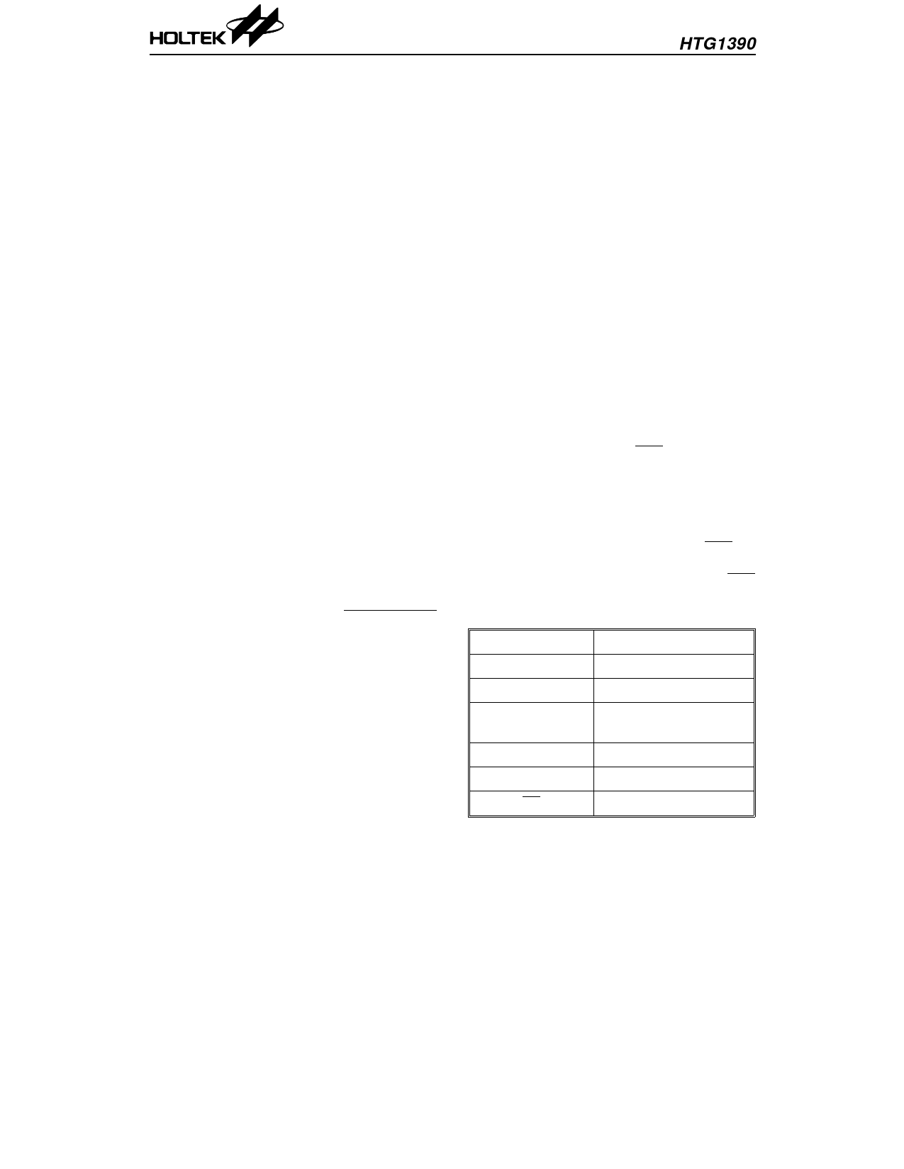
The reset performs the following functions:
PC
000H
TIMER
Stop
Time flag
Reset (Low)
SOUND
Sound off and one sing
mode
Output Port A
high (or floating state)
Interrupt
Disabled
BZ and BZ output Low level
9
17th Nov ’98
Share Link: 