HTG12N0 Просмотр технического описания (PDF) - Holtek Semiconductor
Номер в каталоге
Компоненты Описание
Список матч
HTG12N0 Datasheet PDF : 30 Pages
| |||
HTG12N0
may be enabled or disabled by executing the EI
and DI instructions. If the interrupt is enabled
the timer overflow will cause a subroutine call
to location 4. The state of the timer flag can also
be tested with the conditional jump instruction
JTMR. The timer flag is cleared after the inter-
rupt or the JTMR instruction is executed.
If an internal source is used, the frequency is
determined by the system clock and the pa-
rameter n as defined in the equation. The fre-
quency of the internal frequency source can be
selected by mask option.
Frequency of TIMER clock =
system clock
2n
where n=0,1,2 ...13 selectable by mask option.
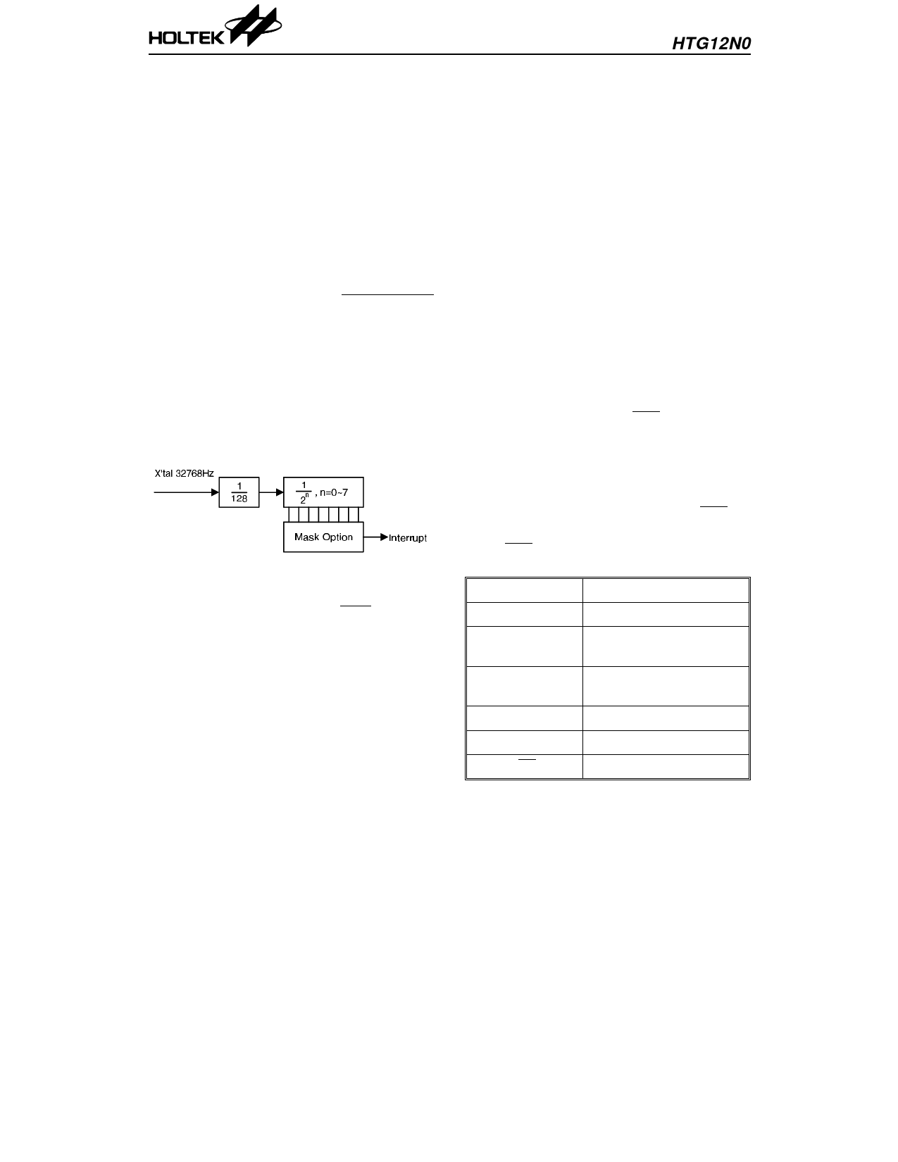
RTC
There is a real time clock (RTC) function imple-
mented on the HTG12N0. The RTC function is used
to generate an accurate time period. The clock source
of RTC circuit comes from the 32768Hz crystal oscil-
lator. The block diagram is shown as follows.
The RTC output can be selected by mask option.
Frequency of the RTC output =
256
2n
,
n=0~7
The RTC output is used to generate an inter-
rupt signal.
Interrupt
The HTG12N0 provides both TIMER and RTC
interrupt modes. The DI and EI instructions
are used to disable and enable the interrupts.
When the RTC is activated during enable inter-
rupt mode and the program is not within a
CALL subroutine, this causes a subroutine call
to location 8 and reset the interrupt latch.
Likewise when the timer flag is set in the en-
able interrupt mode and the program is not
within a CALL subroutine, the TIMER inter-
rupt is activated. This cause a subroutine call to
location 4 and resets the timer flag. If both
TIMER and RTC interrupts arrive at the same
time, the RTC one will be serviced first.
When running under a CALL subroutine or DI
the interrupt acknowledge is on hold until the
RET or EI instruction a invoked. The CALL
instruction should not be used within an inter-
rupt routine as unpredictable behaviors may
occur. If within a CALL subroutine both TIMER
and RTC interrupt occur, no matter what order
they arrive in, the RTC interrupt will be serv-
iced first after leaving the CALL subroutine.
This also applies if the two interrupt arrive at
the same time.
The interrupt are disabled by a hardware reset
or a DI instruction. They remain disabled until
the EI instruction is executed.
Initial reset
The HTG12N0 provides an RES pin for system
initialization. This pin is equipped with an in-
ternal pull high resistor and in combination
with an external 0.1µ~1µF capacitor, it provides
an internal reset pulse of sufficient length to
guarantee a reset to all internal circuits. If the
reset pulse is generated externally, the RES pin
must be held low at least 5ms.
When RES is active, the internal block will be
initialized as shown below:
PC
000H
TIMER
Stop
Timer flag,
Carry flag
Reset (low)
SOUND
Sound off and one sing
mode
Output port A High (or floating state)
LCD output
Disabled
BZ and BZ output High level
11
18th Mar ’99
Share Link: 