74HC132Y Просмотр технического описания (PDF) - STMicroelectronics
Номер в каталоге
Компоненты Описание
Список матч
74HC132Y Datasheet PDF : 13 Pages
| |||
M74HC132
Electrical characteristics
Table 7. AC electrical characteristics
(CL = 50 pF, Input tr = tf = 6 ns)
Test condition
Value
Symbol
Parameter
tTLH, tTHL
Output transition
time
tPLH, tPHL
Propagation delay
time
VCC (V)
2.0
4.5
6.0
2.0
4.5
6.0
TA = 25 °C
Min. Typ. Max.
30 75
8
15
7
13
-
52 105
13 21
11 18
-40 to 85 °C
Min. Max.
95
19
16
-
130
26
22
-55 to 125 °C Unit
Min. Max.
110
22 ns
19
-
160
32 ns
27
Table 8. Capacitive characteristics
Test condition
Value
Sym
Parameter
VCC (V)
TA = 25°C
Min Typ Max
-40 to 85 °C
Min Max
-55 to 125 °C Unit
Min Max
CIN
Input capacitance
CPD
Power dissipation
capacitance(1)
5.0
5
10
10
10
-
-
29
-
pF
1.
CcoPnDsuismdpetfiionnedwiathsotuhtelovaadlue(reoffetrhteo
IC’s
test
internal
circuit).
equivalent capacitance which is calculated
Average operating current can be obtained
from the operating current
by the following equation:
ICC(opr) = CPD x VCC x fIN + ICC/4 (per gate).
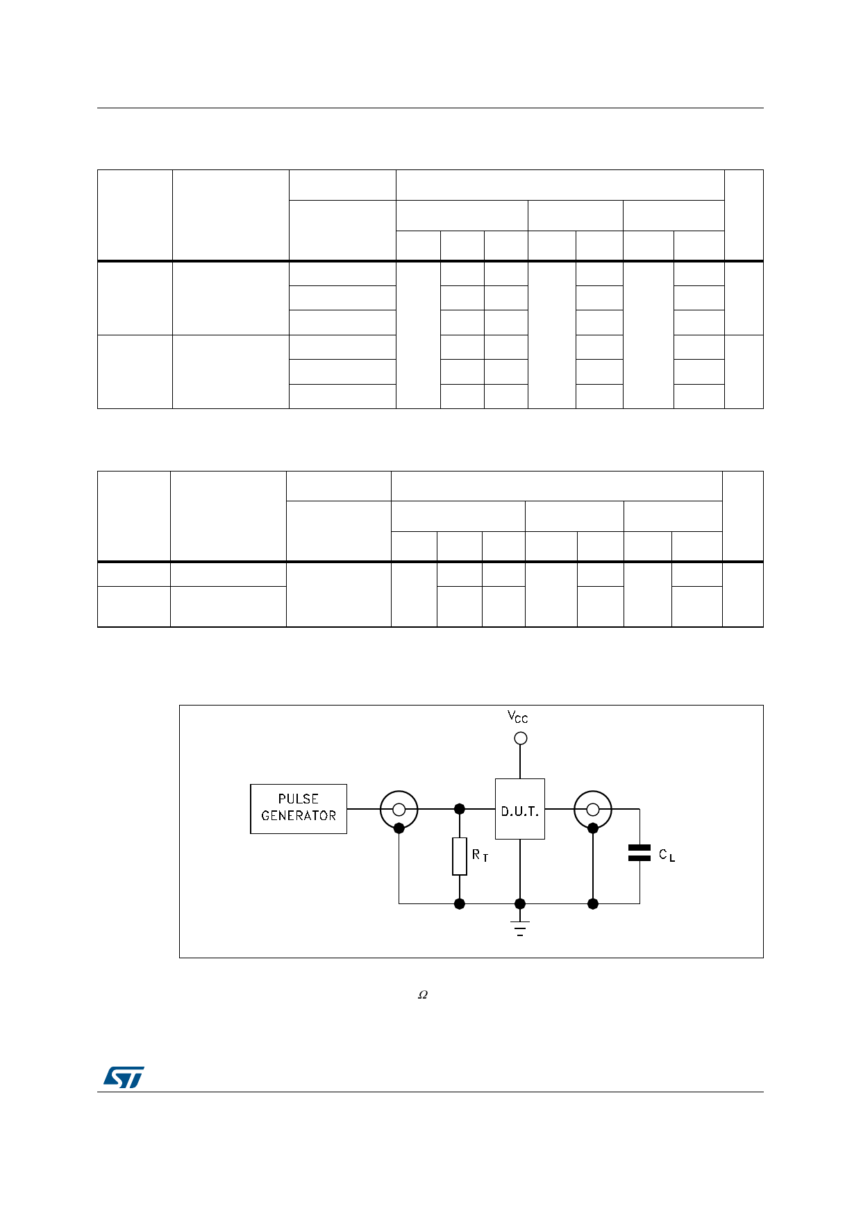
Figure 3. Test circuit
1. Legend:
CRLT
=
=
50 pF or equivalent (includes jig and
ZOUT of pulse generator (typically 50
probe
Ω).
capacitance).
GAMS0301141630CB
DocID1896 Rev 3
7/13
13
Share Link: 