DMS-20LCD-X-5 Просмотр технического описания (PDF) - Murata Manufacturing
Номер в каталоге
Компоненты Описание
Список матч
DMS-20LCD-X-5 Datasheet PDF : 4 Pages
| |||
Functional Specifications (TA = 25ºC)
Input Supply Range
See applicable meter's data sheet
Input Supply Range U1 (LM7805CT) Installed:
DMS-20PC-X-XS
DMS-20PC-X-XL
DMS-20LCD-X-5
DMS-20LCD-X-5B
+7.5 to +12.6V
+7.5 to +32.0V
+7.5 to +32.0V
+7.5 to +12.6V
Operating and Storage Temperature
See applicable meter's data sheet
Humidity
0 to 95%, non-condensing
Dimensions
1.25" (31.8mm)L x 0.75" (19.1mm)H
J1 Connector & Wire Information
Terminal Type
Crimp Tool
Wire Size
Insulation Diameter
Stripping Length
DATEL P/N 39-2099090
DATEL P/N 39-2099000
22 to 26 AWG
0.062" (1.57mm) max.
0.100" to 0.125"
(2.54 to 3.17mm)
Ordering Information
DMS-EB2
DMS-BZL3
DMS-BZL4
39-0304000
39-2359625
Application board with mating connector and terminals
DMS-20 bezel assembly
DMS-20 bezel assembly with sealing gasket
LM7805CT (U1), +5V-output, three-terminal regulator
6-position pc-board socket
TECHNICAL NOTES
1.LCD Backlighting: To backlight a DMS-20LCD meter, connect J1, pin 3
(TEST/HOLD IN) to J1, pin 6 (GND). This allows for external control,
via a switch, of the backlight feature. The switch should be rated for low
voltage operation at 35mA.
2. 9V LCD Meters: DMS-20LCD-X-9 meters cannot be used in a single-
ended configuration, i.e., with (–) IN LO tied to GND. On these models,
both (–) IN LO and (+) IN HI have to be a minimum of 1.5V above and
1.5V below J1 pins 6 and 5, respectively. To operate from a 9V or 12V
battery with (–) IN LO tied to GND, use a 5V-powered meter (DMS-
20LCD-X-5), install U1 (LM7805CT) and open SG4.
3. Input Resistor Dividers: Always use 1%, or better, metal-film resistors
for R1 and R2, and also make sure their power and voltage ratings are
adequate for the given application.
4. Using U1 (LM7805CT): The input power range specified in the Battery
Operation section is rated conservatively assuming a 100mA LED meter
or a 35mA backlit LCD meter. If a non-backlit LCD model or the low-
power LED model is used, the input voltage range can be extended up to
32Vdc.
DMS-EB2
Multi-Purpose Application Board
for DMS-20PC/LCD Meters
A 10μF/35V tantalum capacitor (C2 on schematic) should be installed
with the polarized end next to the + symbol on the DMS-EB2. This is
especially important if the power source is located far from U1.
5. Soldering: DATEL recommends the use of "no-clean" solders when
making modifications to the DMS-EB2.
APPLICATIONS
As shipped, the DMS-EB2 is configured for single-ended operation.
This configuration is preferred for simple voltage measurements and will
generally cover most standard applications. Figure 1 indicates which
solder gaps are shipped closed from the factory.
Simply solder the board onto the meter (pin 1 to pin 1), connect
the power supply to J1, pin 5 (+V) and the power return to J1, pin 6
(GROUND).
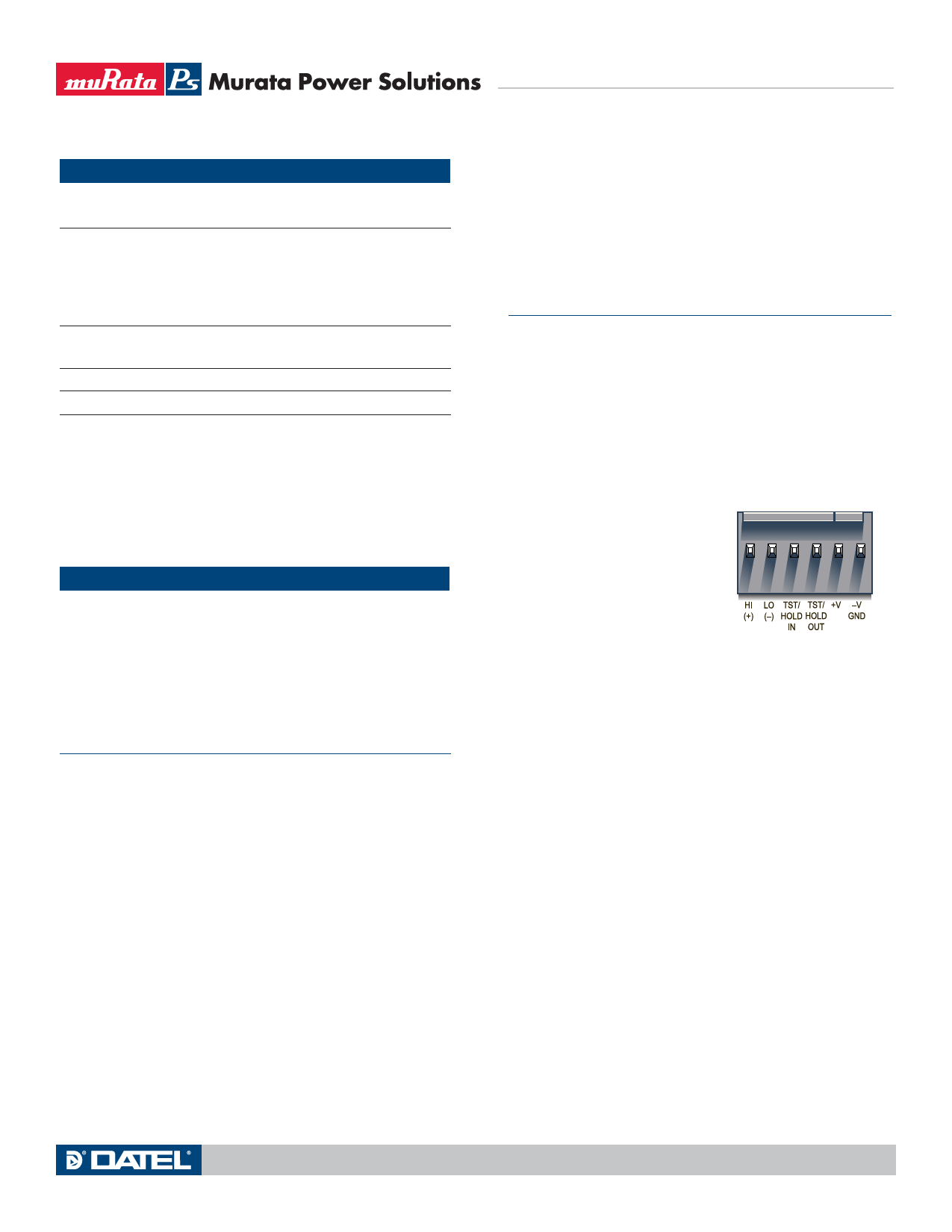
Pin Function
1 (+) INPUT HI
2 (–) INPUT LO
3 TEST/HOLD IN
4 TEST/HOLD OUT
J1
1 23 45 6
5 +V (Positive power connection)
6 –V (Ground, negative power return)
Figure 2. J1 Connector Pinout
1.Decimal Point Placement: DATEL ships the DMS-EB2 with all decimal
point solder gaps (SG1, SG2 and SG3) open. To enable a specific
decimal point, close its respective solder gap with solder. When
re-assigning decimal places for subsequent applications, remember to
unsolder previously closed solder gaps.
Close SG1 for 1.999 (DP1)
Close SG2 for 19.99 (DP2)
Close SG3 for 199.9 (DP3)
2. Display Test (Not Available on LCD Models): Tie pin 4 (TEST/HOLD
OUT) to pin 3 (TEST/HOLD IN) to test the display of the DMS-20PC.
Do not leave the meter in the test mode for more than 10 seconds. On
LED meters with the HOLD option, tying pins 3 and 4 together freezes
the display reading.
3. Battery Operation: Open SG4 and install U1 (LM7805CT) with its metal
tab facing to the left as shown in Figure 3. Allowable input power ranges
(J1, pins 5 and 6) are as follows:
DMS-20PC-X-XS +7.5 to +12.6Vdc
DMS-20PC-X-XL +7.5 to +32Vdc
C2 (10μF/35V) can be added to reduce noise. Observe correct polarity.
Refer to Technical Note 4 for more information.
www.murata-ps.com
Technical enquiries email: sales@murata-ps.com, tel: +1 508 339 3000
MPM_DMS-EB2.E01 Page 2 of 4
Share Link: 