L9822N(1997) Просмотр технического описания (PDF) - STMicroelectronics
Номер в каталоге
Компоненты Описание
Список матч
L9822N Datasheet PDF : 9 Pages
| |||
L9822N
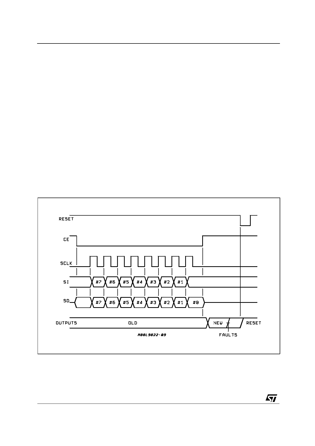
CE Low to High Transition
Once the last data bit has been shifted into the
L9822NSP, the CE pin should be pulled high.
At the rising edge of CE the shift register data is lat-
ched intothe parallel latch and the outputstageswill
be actuated by the new data. An internal 160µs de-
lay timer will also be started at this rising edge (see
tUD). During the 160µs period, the outputs will be
protected only by the analog current limiting circuits
since the resetting of the parallel latches by faults
conditionswill be inhibitedduringthis period.This al-
lows the part to overcome any high inrush currents
that may flow immediately after turn on. Once the
delay period has elapsed, the output voltages are
sensed by the comparators and any output with vol-
tageshigher than 1.8V arelatched OFF. It shouldbe
noted that the SCLK pin should be low at both tran-
sitions of the CE pin to avoid any false clocking of
the shift register. The SCLK inputis gatedby the CE
pin, so that the SCLK pin is ignored whenever the
CE pin is high.
FAULT CONDITIONS CHECK
Checking for fault conditions may be done in the fol-
lowing way. Clock in a new control byte. Wait 160
microseconds or so to allow the outputs to settle.
Clock in thesame controlbyte and observethe diag-
nostic data that comes out of the device. The diag-
nostic bits should be identical to the bits that were
first clockedin. Any differenceswould point to a fault
on that output.If the outputwas programmed ON by
clocking in a zero, and a one came back as the dia-
gnosticbit forthat output,the outputpinwasstill high
and a short circuit or overload condition exists. If the
output was programmed OFF by clocking in a one,
and a zero came back as the diagnostic bit for that
output, nothing had pulled the output pin high and it
must be floating, so an open circuit condition exists
for that output.
Figure 1 : Byte Timing with Asynchronous Reset.
6/9
Share Link: 