LT1175-5 Просмотр технического описания (PDF) - Linear Technology
Номер в каталоге
Компоненты Описание
Список матч
LT1175-5 Datasheet PDF : 38 Pages
| |||
LTC1966
Applications Information
RMS-TO-DC CONVERSION
Definition of RMS
RMS amplitude is the consistent, fair and standard way to
measure and compare dynamic signals of all shapes and
sizes. Simply stated, the RMS amplitude is the heating
potential of a dynamic waveform. A 1VRMS AC waveform
will generate the same heat in a resistive load as will 1V DC.
1V DC +– R
1V ACRMS
R
SAME
HEAT
1V (AC + DC) RMS
R
1966 F01
Figure 1
Mathematically, RMS is the root of the mean of the square:
VRMS = V2
Alternatives to RMS
Other ways to quantify dynamic waveforms include peak
detection and average rectification. In both cases, an aver-
age (DC) value results, but the value is only accurate at
the one chosen waveform type for which it is calibrated,
typically sine waves. The errors with average rectification
are shown in Table 1. Peak detection is worse in all cases
and is rarely used.
Table 1. Errors with Average Rectification vs True RMS
WAVEFORM
VRMS
AVERAGE
RECTIFIED
(V)
ERROR*
Square Wave
1.000
1.000 11%
Sine Wave
1.000
0.900 *Calibrate for 0% Error
Triangle Wave
1.000
0.866 –3.8%
SCR at 1/2 Power,
Θ = 90°
1.000
0.637 –29.3%
SCR at 1/4 Power,
Θ = 114°
1.000
0.536 –40.4%
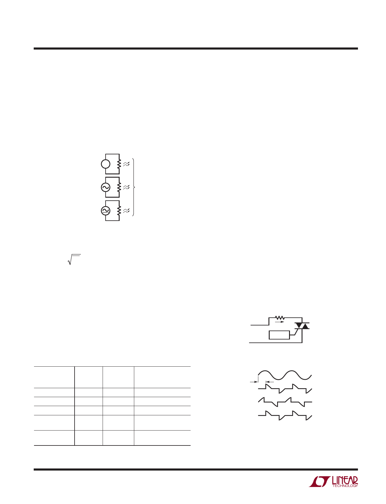
The last two entries of Table 1 are chopped sine waves as
is commonly created with thyristors such as SCRs and
Triacs. Figure 2a shows a typical circuit and Figure 2b
shows the resulting load voltage, switch voltage and load
currents. The power delivered to the load depends on the
firing angle, as well as any parasitic losses such as switch
ON voltage drop. Real circuit waveforms will also typically
have significant ringing at the switching transition, depen-
dent on exact circuit parasitics. For the purposes of this
data sheet, SCR waveforms refers to the ideal chopped
sine wave, though the LTC1966 will do faithful RMS-to-DC
conversion with real SCR waveforms as well.
The case shown is for Θ = 90°, which corresponds to 50%
of available power being delivered to the load. As noted in
Table 1, when Θ = 114°, only 25% of the available power
is being delivered to the load and the power drops quickly
as Θ approaches 180°.
With an average rectification scheme and the typical
calibration to compensate for errors with sine waves, the
RMS level of an input sine wave is properly reported; it
is only with a nonsinusoidal waveform that errors occur.
Because of this calibration, and the output reading in
VRMS, the term true RMS got coined to denote the use of
an actual RMS-to-DC converter as opposed to a calibrated
average rectifier.
+ VLOAD –
AC
MAINS
+
VLINE
–
ILOAD
CONTROL
Figure 2a
+
– VTHY
1966 F02a
VLINE
Θ
VLOAD
VTHY
ILOAD
Figure 2b
1966 F02b
1966fb
10
Share Link: 