RT9167-15CB Просмотр технического описания (PDF) - Richtek Technology
Номер в каталоге
Компоненты Описание
Список матч
RT9167-15CB Datasheet PDF : 14 Pages
| |||
RT9167/A
Applications Guides
Capacitor Selection and Regulator Stability
Like any low-dropout regulator, the external capacitors
used with the RT9167/A must be carefully selected for
regulator stability and performance.
Using a capacitor whose value is > 1µF on the
RT9167/A input and the amount of capacitance can be
increased without limit. The input capacitor must be
located a distance of not more than 0.5" from the input
pin of the IC and returned to a clean analog ground.
Any good quality ceramic or tantalum can be used for
this capacitor. The capacitor with larger value and
lower ESR (equivalent series resistance) provides
better PSRR and line-transient response.
The output capacitor must meet both requirements for
minimum amount of capacitance and ESR in all LDOs
application. The RT9167/A is designed specifically to
work with low ESR ceramic output capacitor in space-
saving and performance consideration. Using a
ceramic capacitor whose value is at least 1uF with
ESR is > 5mΩ on the RT9167/A output ensures
stability. The RT9167/A still works well with output
capacitor of other types due to the wide stable ESR
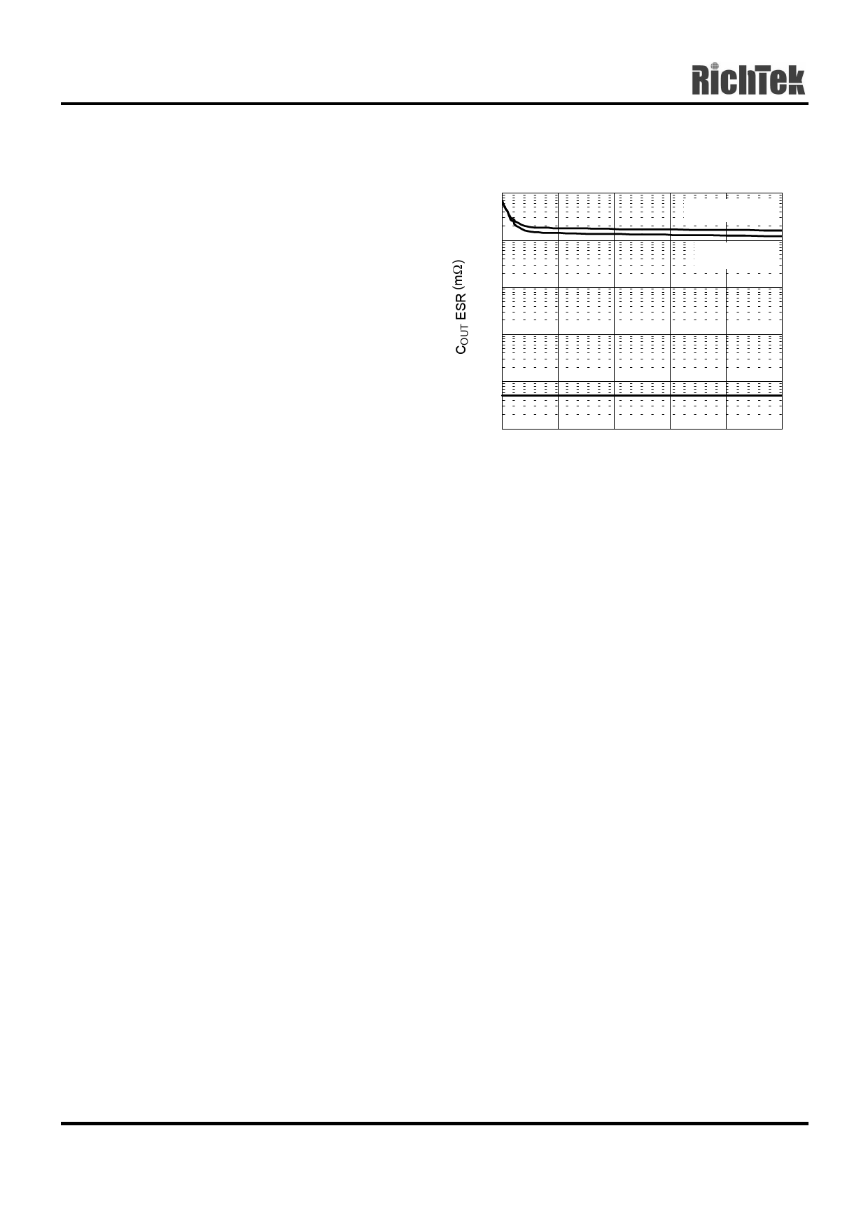
range. Fig.1 shows the curves of allowable ESR range
as a function of load current for various output
voltages and capacitor values. Output capacitor of
larger capacitance can reduce noise and improve
load-transient response, stability, and PSRR. The
output capacitor should be located not more than
0.5" from the VOUT pin of the RT9167/A and returned
to a clean analog ground.
www.richtek-ic.com.tw
8
Region of Stable COUT ESR vs. Load Current
100
COUT = 4.7µF
10
COUT = 1µF
1
0.1
0.01
0.001
0
40
80
120
160
200
Load Current (mA)
Fig. 1
Note that some ceramic dielectrics exhibit large
capacitance and ESR variation with temperature. It
may be necessary to use 2.2µF or more to ensure
stability at temperatures below -10°C in this case. Also,
tantalum capacitors, 2.2µF or more may be needed to
maintain capacitance and ESR in the stable region for
strict application environment.
Tantalum capacitors maybe suffer failure due to surge
current when it is connected to a low-impedance
source of power (like a battery or very large capacitor).
If a tantalum capacitor is used at the input, it must be
guaranteed to have a surge current rating sufficient for
the application by the manufacture.
Use a 10nF bypass capacitor at BP for low output
voltage noise. The capacitor, in conjunction with an
internal 200KΩ resistor, which connects bypass pin
and the band-gap reference, creates an 80Hz low-
pass filter for noise reduction. Increasing the
capacitance will slightly decrease the output noise,
but increase the start-up time. The capacitor
connected to the bypass pin for noise reduction must
have very low leakage. This capacitor leakage
current causes the output voltage to decline by a
proportional amount to the current due to the voltage
drop on the internal 200KΩ resistor. Fig. 2 shows the
power on response.
DS9167/A-10 July 2001
Share Link: 