AP1703EWG-7 Просмотр технического описания (PDF) - Diodes Incorporated.
Номер в каталоге
Компоненты Описание
Список матч
AP1703EWG-7 Datasheet PDF : 9 Pages
| |||
AP1701/2/3/4
3-PIN MICROPROCESSOR RESET CIRCUITS
Function Description
A microprocessor’s (µP’s) reset input starts the µP in a
known state. The AP1701/2/3/4 assert reset to prevent
code-execution errors during power-up, power-down, or
brownout conditions. They assert a reset signal whenever the VCC
supply voltage declines below a preset threshold, keeping it
asserted for at least 240ms after VCC has risen above the reset
threshold. The AP1701/2/3/4 have a push-pull output stage.
Applications Information
Negative-Going VCC Transients
In addition to issuing a reset to the µP during power-up,
power-down, and brownout conditions, the AP1701/2/3/4 are
relatively immune to short-duration negative-going VCC transients
(glitches).
The AP1701/2/3/4 do not generate a reset pulse. The
graph was generated using a negative going pulse applied to VCC,
starting 0.5V above the actual reset threshold and ending below it
by the magnitude indicated (reset comparator overdrive). The
graph indicates the maximum pulse width a negative going VCC
transient can have without causing a reset pulse. As the
magnitude of the transient increases (goes farther below the
reset threshold), the maximum allowable pulse width decreases.
Typically, a VCC transient that goes 100mV below the reset
threshold and lasts 100µs or less will not cause a reset pulse. A
0.1µF bypass capacitor mounted as close as possible to the VCC
pin provides additional transient immunity.
Ensuring a Valid Reset Output
Down to VCC = 0
RESET is guaranteed to be a logic low for VCC > 1V.
Once VCC exceeds the reset threshold, an internal timer keeps
RESET low for the reset timeout period; after this interval,
RESET goes high. If a brownout condition occurs (VCC dips
RESET
below the reset threshold), RESET goes low. Any time VCC
goes below the reset threshold, the internal timer resets to zero,
and RESET goes low. The internal timer starts after VCC
returns above the reset threshold, and RESET remains low
for the reset timeout period.
When VCC falls below 1V, the AP1701/3 RESET
output no longer sinks current—it becomes an open circuit.
Therefore, high-impedance CMOS logic inputs connected to
RESET can drift to undetermined voltages.
This presents no problem in most applications since most µP and
other circuitry is inoperative with VCC below 1V. However, in
applications where RESET must be valid down to 0V, adding a
pull down resistor to RESET causes any stray leakage
currents to flow to ground, holding RESET low. R1’s value is
not critical; 100k are large enough not to load RESET and
small enough to pull RESET to ground. For the AP1702/4 if
RESET is required to remain valid for VCC < 1V.
Benefits of Highly Accurate Reset Threshold
Most µP supervisor ICs has reset threshold voltages
between 5% and 10% below the value of nominal supply voltages.
This ensures a reset will not occur within 5% of the nominal
supply, but will occur when the supply is 10% below nominal.
When using ICs rated at only the nominal supply ±5%, this leaves
a zone of uncertainty where the supply is between 5% and 10%
low, and where the reset may or may not be asserted.
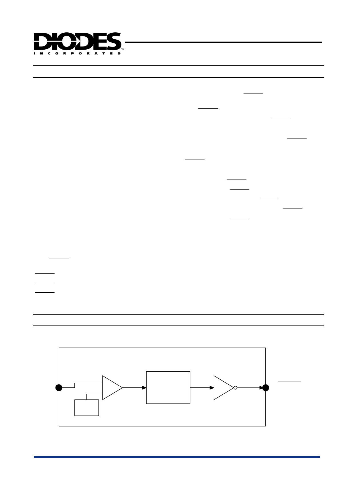
Block Diagram
VREF
AP1701/2/3/4 Rev. 2
Delay Circuit
Driver
RESET
/ RESET
4 of 9
www.diodes.com
FEBRUARY 2007
© Diodes Incorporated
Share Link: 