HMC539LP3 Просмотр технического описания (PDF) - Analog Devices
Номер в каталоге
Компоненты Описание
Список матч
HMC539LP3 Datasheet PDF : 6 Pages
| |||
HMC539LP3 / 539LP3E
v00.0605
0.25 dB LSB GaAs MMIC 5-BIT DIGITAL
POSITIVE CONTROL ATTENUATOR, DC - 4 GHz
5
Typical Applications
Features
The HMC539LP3 / HMC539LP3E is ideal for both RF
and IF applications:
• Cellular Infrastructure
• ISM, MMDS, WLAN, WiMAX, WiBro
• Microwave Radio & VSAT
• Test Equipment and Sensors
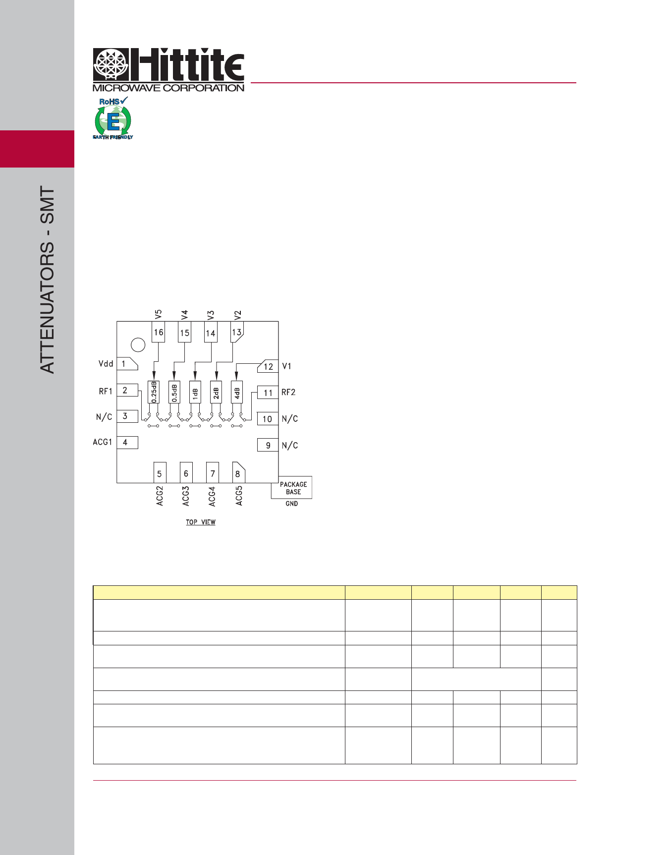
Functional Diagram
0.25 dB LSB Steps to 7.75 dB
± 0.05 dB Typical Step Error
Low Insertion Loss: 0.7 dB
High IP3: +50 dBm
Single Control Line Per Bit
TTL/CMOS Compatible Control
Single +5V Supply
3x3 mm SMT Package
General Discription
The HMC539LP3 & HMC539LP3E are broadband
5-bit GaAs IC digital attenuators in low cost lead-
less surface mount packages. This single positive
control line per bit digital attenuator utilizes an off
chip AC ground capacitor for near DC operation,
making it suitable for a wide variety of RF and IF
applications. Covering DC to 4 GHz, the insertion loss
is less than 0.7 dB typical. The attenuator bit values
are 0.25 (LSB), 0.5, 1, 2, and 4 dB for a total attenu-
ation of 7.75 dB. Attenuation accuracy is excellent
at ± 0.05 dB typical step error. The attenuator also
features a high IIP3 of +50 dBm. Five TTL/CMOS
control inputs are used to select each attenuation
state. A single Vdd bias of +5V is required.
Electrical Specifications,
TA = +25° C, With Vdd = +5V & Vctl = 0/+5V (Unless Otherwise Noted)
Parameter
Insertion Loss
Attenuation Range
Return Loss (RF1 & RF2, All Atten. States)
Attenuation Accuracy:
(Referenced to Insertion Loss)
Input Power for 0.1 dB Compression
Input Third Order Intercept Point
(Two-Tone Input Power= 0 dBm Each Tone)
Switching Characteristics
tRISE, tFALL (10/90% RF)
tON, tOFF (50% CTL to 10/90% RF)
Frequency (GHz)
DC - 1.5 GHz
1.5 - 3.0 GHz
3.0 - 4.0 GHz
DC - 4 GHz
DC - 3 GHz
3.0 - 4.0 GHz
All States
DC - 3 GHz
3.0 - 4.0 GHz
0.1 - 4.0 GHz
Min.
Typ.
Max.
0.7
1.0
1.0
1.3
1.3
1.7
7.75
25
20
± (0.2 + 2% of Atten. Setting) Max.
± (0.2 + 4% of Atten. Setting) Max.
28
0.1 - 4.0 GHz
50
DC - 4 GHz
48
52
Units
dB
dB
dB
dB
dB
dB
dB
dB
dBm
dBm
ns
ns
5 - 164
For price, delivery, and to place orders, please contact Hittite Microwave Corporation:
20 Alpha Road, Chelmsford, MA 01824 Phone: 978-250-3343 Fax: 978-250-3373
Order On-line at www.hittite.com
Share Link: 