VS-70HF10 Просмотр технического описания (PDF) - Vishay Semiconductors
Номер в каталоге
Компоненты Описание
Список матч
VS-70HF10 Datasheet PDF : 9 Pages
| |||
www.vishay.com
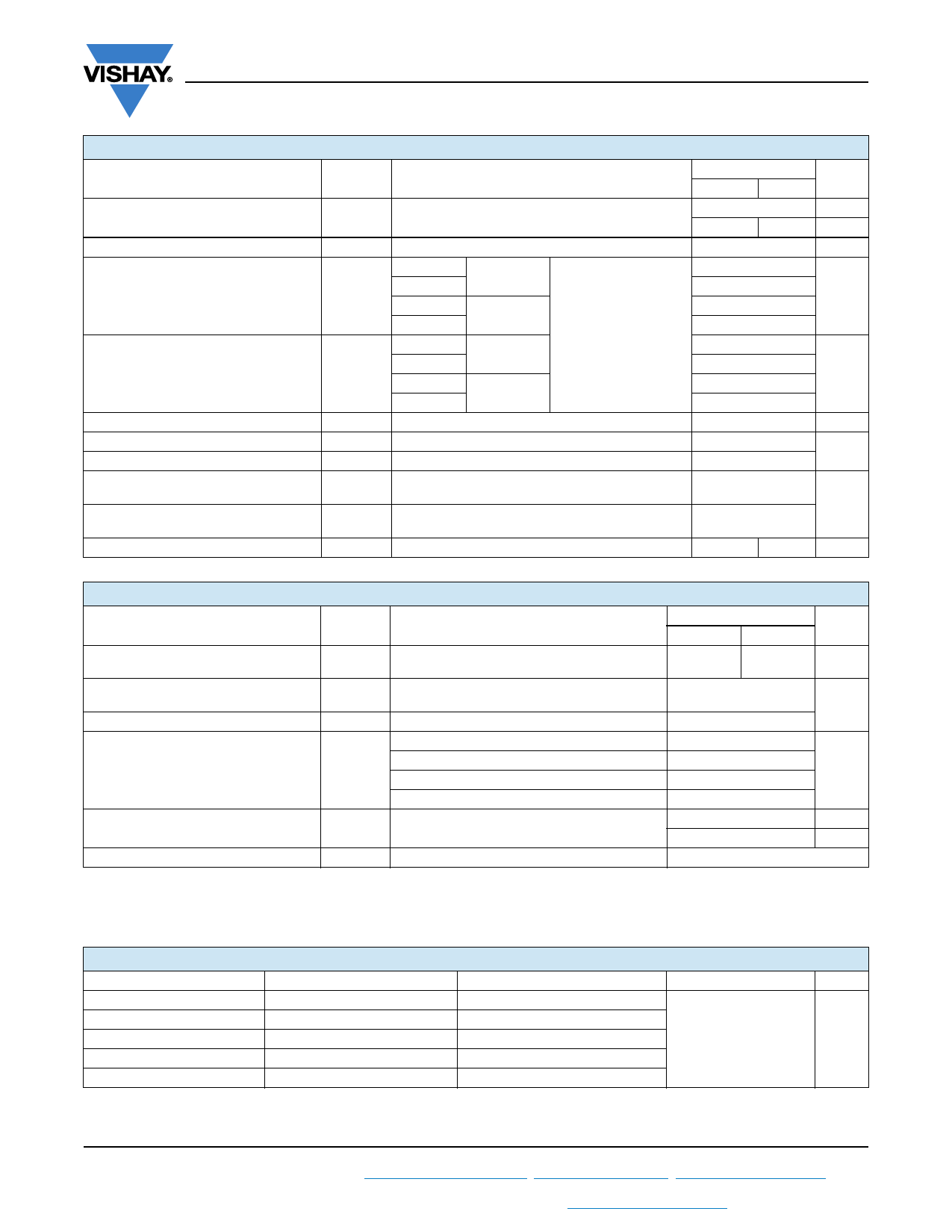
VS-70HF(R) Series
Vishay Semiconductors
FORWARD CONDUCTION
PARAMETER
Maximum average forward current
at case temperature
Maximum RMS forward current
Maximum peak, one cycle forward,
non-repetitive surge current
Maximum I2t for fusing
Maximum I2t for fusing
Low level value of threshold voltage
High level value of threshold voltage
Low level value of forward
slope resistance
High level value of forward
slope resistance
Maximum forward voltage drop
SYMBOL
IF(AV)
IF(RMS)
IFSM
I2t
I2t
VF(TO)1
VF(TO)2
rf1
rf2
VFM
TEST CONDITIONS
180° conduction, half sine wave
t = 10 ms No voltage
t = 8.3 ms reapplied
t = 10 ms
t = 8.3 ms
t = 10 ms
t = 8.3 ms
100 % VRRM
reapplied
No voltage
reapplied
Sinusoidal half wave,
initial TJ = TJ maximum
t = 10 ms 100 % VRRM
t = 8.3 ms reapplied
t = 0.1 ms to 10 ms, no voltage reapplied
(16.7 % x x IF(AV) < I < x IF(AV)), TJ = TJ maximum
(I > x IF(AV)), TJ = TJ maximum
70HF(R)
10 to 120 140/160
70
140
110
110
1200
1250
1000
1050
7100
6450
5000
4550
71 000
0.79
1.00
UNITS
A
°C
A
A
A2s
A2s
V
(16.7 % x x IF(AV) < I < x IF(AV)), TJ = TJ maximum
2.33
m
(I > x IF(AV)), TJ = TJ maximum
1.53
Ipk = 220 A, TJ = 25 °C, tp = 400 μs rectangular wave 1.35
1.46
V
THERMAL AND MECHANICAL SPECIFICATIONS
PARAMETER
SYMBOL
TEST CONDITIONS
Maximum junction and
storage temperature range
Maximum thermal resistance,
junction to case
Thermal resistance, case to heatsink
Maximum allowable mounting torque
(+0 %, -10 %)
TJ, TStg
RthJC
RthCS
DC operation
Mounting surface, smooth, flat and greased
Not lubricated thread, tighting on nut (1)
Lubricated thread, tighting on nut (1)
Not lubricated thread, tighting on hexagon (2)
Lubricated thread, tighting on hexagon (2)
Approximate weight
Case style
Notes
(1) Recommended for pass-through holes
(2) Recommended for holed threaded heatsinks
See dimensions - link at the end of datasheet
70HF(R)
UNITS
10 to 120 140/160
-65 to +180 -65 to +150 °C
0.45
K/W
0.25
3.4 (30)
2.3 (20)
4.2 (37)
N·m
(lbf · in)
3.2 (28)
17
g
0.6
oz.
DO-5 (DO-203AB)
RthJC CONDUCTION
CONDUCTION ANGLE
180°
120°
90°
60°
30°
SINUSOIDAL CONDUCTION
0.08
0.10
0.13
0.19
0.30
RECTANGULAR CONDUCTION
0.06
0.11
0.14
0.20
0.30
TEST CONDITIONS
TJ = TJ maximum
Note
• The table above shows the increment of thermal resistance RthJC when devices operate at different conduction angles than DC
UNITS
K/W
Revision: 11-Jan-18
2
Document Number: 93521
For technical questions within your region: DiodesAmericas@vishay.com, DiodesAsia@vishay.com, DiodesEurope@vishay.com
THIS DOCUMENT IS SUBJECT TO CHANGE WITHOUT NOTICE. THE PRODUCTS DESCRIBED HEREIN AND THIS DOCUMENT
ARE SUBJECT TO SPECIFIC DISCLAIMERS, SET FORTH AT www.vishay.com/doc?91000
Share Link: 