LC4104C Просмотр технического описания (PDF) - SANYO -> Panasonic
Номер в каталоге
Компоненты Описание
Список матч
LC4104C Datasheet PDF : 9 Pages
| |||
LC4104C
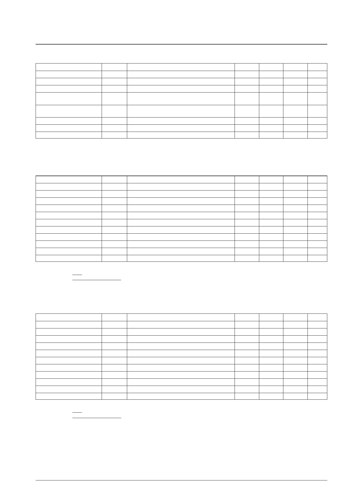
Allowable Operating Ranges at Ta = –20 to +75°C, VSS = 0 V
Parameter
Symbol
Conditions
min
typ
Supply voltage
Supply voltage
Supply voltage
Input high-level voltage
VDD
VDDH
VSS
VIH
D0 to D7, LOAD, CP, R/L, M, TEST, DISP, BS,
EIO1, EIO2
2.7
20
0
0.8 VDD
D0 to D7, LOAD, CP, R/L, M, TEST, DISP, BS,
Input low-level voltage
VIL
EIO1, EIO2
0
Input voltage
Input voltage
V0, V2
V3
V0, V2
V3
VDDH – 7
0
Input voltage
V5
V5
0
Note: V0, V2, V3, and V5 must obey the following inequalities: VDDH ≥ V0 ≥ V2 ≥ VDDH – 7 V, and 7 V ≥ V3 ≥ V5 ≥ VSS.
At power on: First turn on the logic system power supply and then turn on the high-voltage system power supply.
At power off: First turn off the high-voltage system power supply and then turn off the logic system power supply.
Allowable Operating Ranges at Ta = –20 to +75°C, VSS = 0 V, VDD = 5 V ± 10%
Parameter
Symbol
Conditions
CP clock frequency
fcp
CP
High-level load pulse width
tw (ldH) LOAD
High-level clock pulse width
tw (cpH) CP
Low-level clock pulse width
tw (cpL) CP
LOAD/CP setup time
tsu (ld) LOAD, CP
LOAD/CP hold time
tho (ld) LOAD, CP
DATA/CP setup time
tsu (cp) CP, D0 to D7
DATA/CP hold time
tho (cp) CP, D0 to D7
EIO input setup time
tsu (ei) CP, EIO1, EIO2
Clock rise time
tr
LOAD, CP*
Clock fall time
tf
LOAD, CP*
Note: * The clock rise time (tr) and fall time (tf) must obey inequalities and y below.
1
fcp – tw (cph) – tw (cpl)
: tr, tf <
2
y: tr, tf ≤ 50 ns
min
typ
50
20
20
100
200
10
10
24
Allowable Operating Ranges at Ta = –20 to +75°C, VSS = 0 V, VDD = 2.7 to 4.5 V
Parameter
Symbol
Conditions
CP clock frequency
fcp
CP
High-level load pulse width
tw (ldH) LOAD
High-level clock pulse width
tw (cpH) CP
Low-level clock pulse width
tw (cpL) CP
LOAD/CP setup time
tsu (ld) LOAD, CP
LOAD/CP hold time
tho (ld) LOAD, CP
DATA/CP setup time
tsu (cp) CP, D0 to D7
DATA/CP hold time
tho (cp) CP, D0 to D7
EIO input setup time
tsu (ei) CP, EIO1, EIO2
Clock rise time
tr
LOAD, CP*
Clock fall time
tf
LOAD, CP*
Note: * The clock rise time (tr) and fall time (tf) must obey inequalities and y below.
1
: tr, tf <
fcp
– tw (cph) – tw (cpl)
2
y: tr, tf ≤ 50 ns
min
typ
50
37
37
100
200
35
35
30
max
Unit
5.5
V
36
V
V
VDD
V
0.2 VDD
V
VDDH
V
VSSH + 7
V
V
max
Unit
12
MHz
ns
ns
ns
ns
ns
ns
ns
ns
50
ns
50
ns
max
Unit
10
MHz
ns
ns
ns
ns
ns
ns
ns
ns
50
ns
50
ns
No. 5194-3/9
Share Link: 