FP6321 Просмотр технического описания (PDF) - Unspecified
Номер в каталоге
Компоненты Описание
Список матч
FP6321 Datasheet PDF : 13 Pages
| |||
fitipower integrated technology lnc.
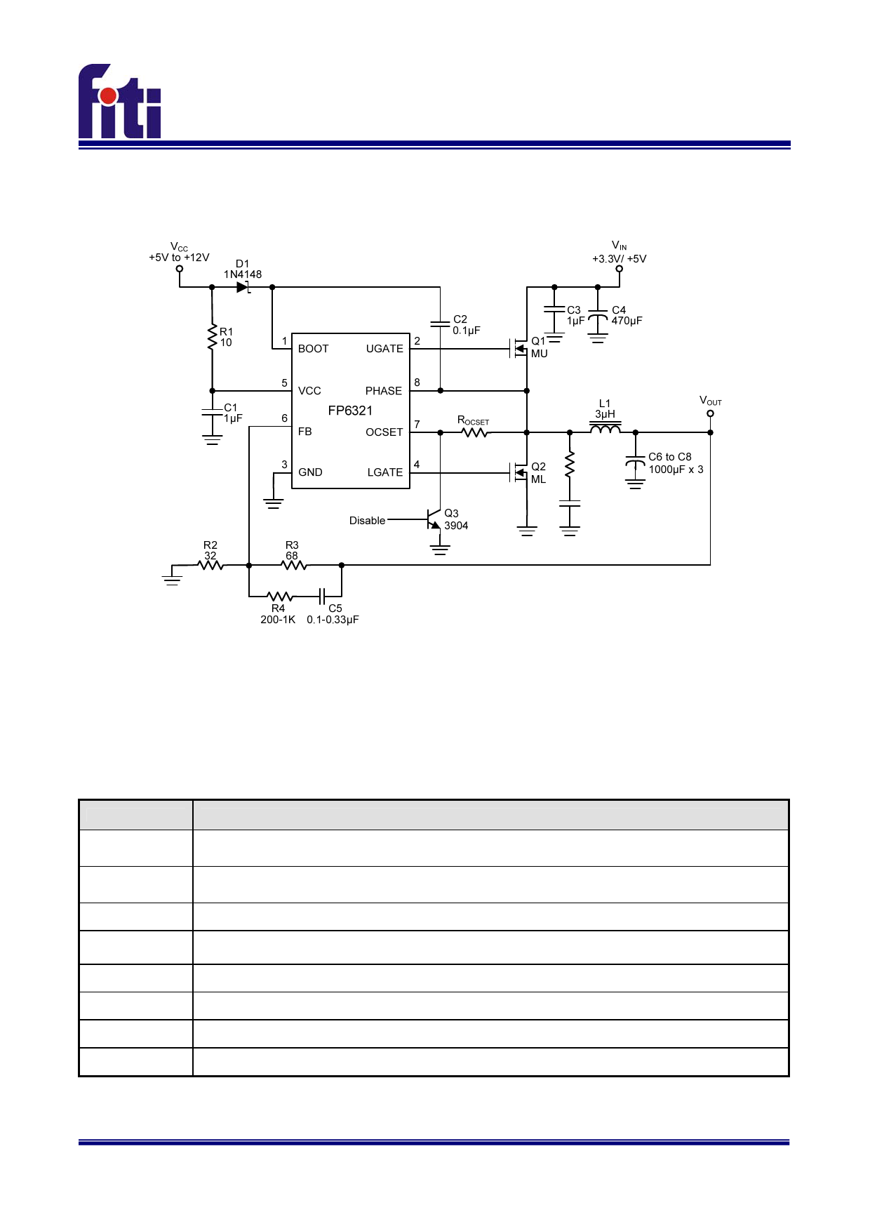
Typical Application Circuit
FP6321
Figure 2. Typical Application Circuit of FP6321
Note: It is not recommended to apply FP6321 on VCC=12V/ VIN =12V condition
Functional Pin Description
Pin Name
BOOT
UGATE
GND
LGATE
VCC
FB
OCSET
PHASE
Pin Function
This pin provides bias voltage to the high side MOSFET Driver. A bootstrap circuit may be to create a BOOT
voltage suitable to drive a standard N-Channel MOSFET.
Connect UGATE to the high side MOSFET gate. This pin is monitored by the adaptive shoot-through protection
circuitry to determine when the high side MOSFET has turned off.
Ground.
Connect LGATE to the low side MOSFET gate. This pin is monitored by the adaptive shoot-through protection
circuitry to determine when the high side MOSFET has turned off.
Power Pin.
Feedback Pin. The typical reference voltage is 0.8V.
Shutdown Control and connect a resistance (ROCSET) for over current setting.
Connect the PHASE pin to the high side MOSFET source, and sensing converter’s input power.
FP6321-1.3 -FEB-2010
2
Share Link: 