ML4863 Просмотр технического описания (PDF) - Micro Linear Corporation
Номер в каталоге
Компоненты Описание
Список матч
ML4863 Datasheet PDF : 10 Pages
| |||
FUNCTIONAL DESCRIPTION
The ML4863 utilizes a flyback topology with constant on-
time control. The circuit determines the length of the off-
time by waiting for the inductor current to drop to a level
determined by the feedback voltage (VFB). Consequently,
the current programming is somewhat unconventional
because the valley of the current ripple is programmed
instead of the peak. The controller automatically enters
burst mode when the programmed current falls below
zero. Constant on-time control therefore features a
transition into and out of burst mode which does not
require additional control circuitry.
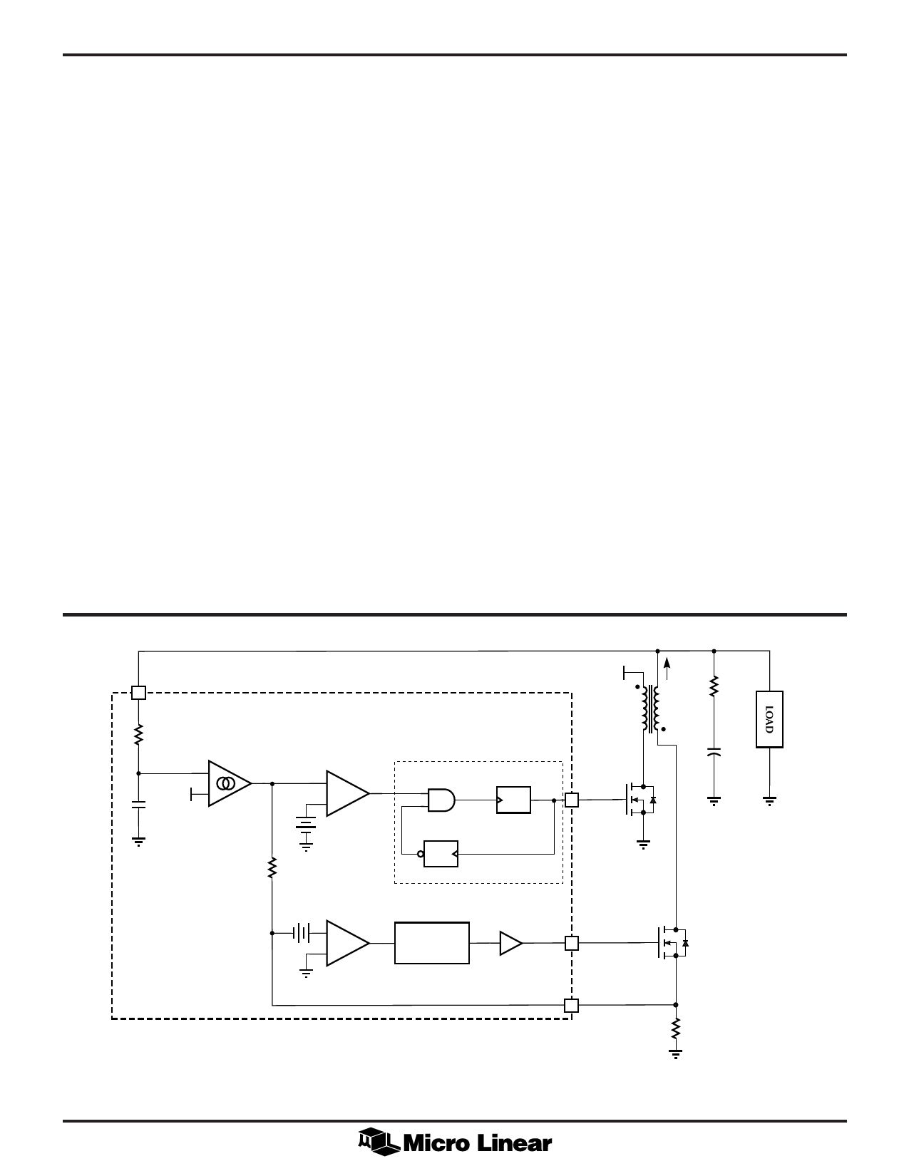
The control circuit is made up of four distinctive blocks;
the constant on-time oscillator, the current programming
comparator, the feedback transconductance amplifier, and
the synchronous rectifier controller. A simplified circuit
diagram is shown in Figure 1.
OSCILLATOR & COMPARATOR
The oscillator has a constant on-time and a minimum off-
time. The off-time is extended as long as the output of the
current programming comparator is low. Note that in
constant on-time control, a discharge (off-time) cycle is
needed for the inductor current to be sensed. The
minimum off-time is required to account for the finite
circuit delays in sensing the inductor output current.
ML4863
TRANSCONDUCTANCE AMPLIFIER
The feedback transconductance amplifier generates a
current from the voltage difference between the output
and the reference. This current produces a voltage across
Rgm that adds to the negative voltage on the current sense
resistor, RSENSE. When the current level in the inductor
drops low enough to cause the voltage at the non-inverting
input of the current programming comparator to go
positive, the comparator trips and the converter starts a
new on-cycle. The current programming comparator
controls the length of the off-time by waiting until the
current in the secondary decreases to the value specified
by the feedback transconductance amplifier.
In this way, the feedback transconductance amplifier‘s
output current steers the current level in the inductor.
When the output voltage drops due to a load increase, it
will increase the output current of the feedback amplifier
and generate a larger voltage across Rgm which in turn
raises the secondary current trip level. However, when the
output voltage is too high, the feedback amplifier’s output
current will eventually become negative. Because the
output current of the inductor can never go negative by
virtue of the diode, the non-inverting input of the
comparator will also stay negative. This causes the
converter to stop operation until the output voltage drops
enough to increase the output current of the feedback
transconductance amplifier above zero.
4
VFB
FEEDBACK
RP TRANSCONDUCTANCE
AMPLIFIER
+
VREF
–
CP
CURRENT
PROGRAMMING
COMPARATOR
+
COMP
–
CONSTANT ON-TIME
MINIMUM OFF-TIME
OSCILLATOR
VIN
IS
LP 1:1
RESR
C
ONE SHOT
tON
2.5µs
OUT 1
6
ONE SHOT
tOFF
500ns
Rgm
RECTIFIER
COMPARATOR
–
COMP
+
BLANKING
OUT 2
7
A2
ML4863
SENSE
2
RSENSE
VOUT
Figure 1. Schematic of the ML4863 Controller and Power Stage
5
Share Link: 