MB86615 Просмотр технического описания (PDF) - Fujitsu
Номер в каталоге
Компоненты Описание
Список матч
MB86615 Datasheet PDF : 48 Pages
| |||
MB86615
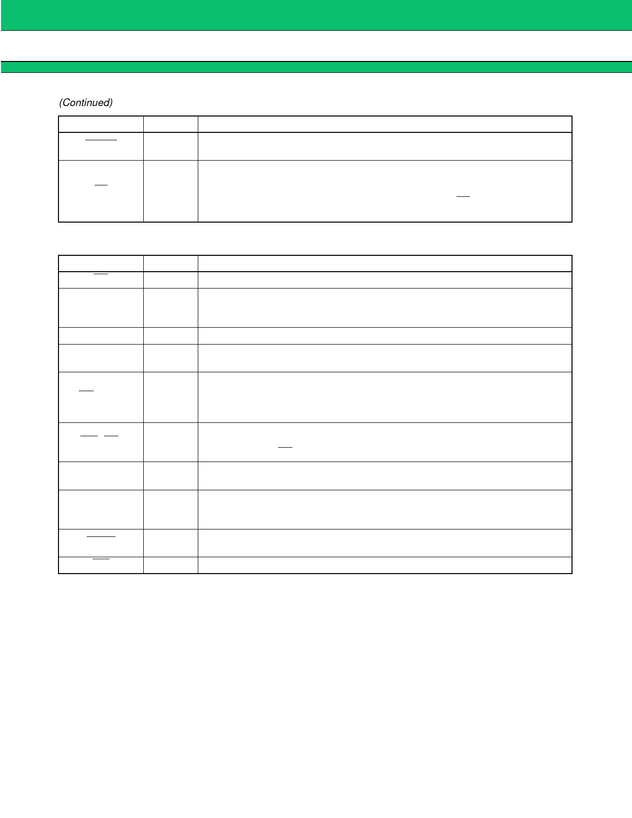
(Continued)
Pin name
I/O
ICREC
O
FP
I/O
3. System Interface
Pin name
I/O
CS
I
A5 to A1
I
D15 to D6, D0
I/O
AD5 to AD1
I/O
RD (R/W)
I
WR (DS)
I
ALE
I
DREQ
O
DACK
I
INT
O
Function
This pin outputs a signal indicating that data sent in the reception mode is data in
a packet from which a data-CRC error has been detected.
Time stamp trigger signal I/O pin.
Transmission mode: This pin inputs the time stamp trigger signal.
The value in the internal cycle timer register is fetched upon
detection of the falling edge of the FP signal.
Reception mode: Time stamp match detection signal output pin.
Function
Input pin for signals used by the MPU to select the MB86615 as an I/O device.
Address input pins for internal register selection.
Valid only in non-multiplexed mode.
If multiplexed mode is selected these pins should be fixed at ‘0’.
16-bit data bus input/output pins (MSB is D15, LSB is D0).
16-bit data bus input/output pins (MSB is AD5, LSB is AD1). Used for address
input signals when multiplexed mode is selected.
80-series mode: Read strobe signal input pin, used to output data from the
MB86615 to the data bus.
68-series mode: Control signal input pin, used for data input/output operations to
the MB86615.
80-series mode: Write strobe signal input pin, used to input data from the data
bus to the MB86615.
68-series mode: DS signal input pin, output when data bus is enabled.
ALE signal input pin, for signal output when addresses are enabled in multiplexed
mode. In non-multiplexed mode, this signal should be fixed at ‘0’.
This pin outputs the DMA transfer request signal to the DMAC for asynchronous
transfer in DMA mode.
The signal requests DMA transfer between the device and memory.
This pin inputs the DMA enable signal from the DMAC for asynchronous transfer
in DMA mode.
Interrupt output pin.
10
Share Link: 