MX641 Просмотр технического описания (PDF) - CML Microsystems Plc
Номер в каталоге
Компоненты Описание
Список матч
MX641 Datasheet PDF : 17 Pages
| |||
Dual SPM Detector
Page 7 of 16
MX641 Preliminary Information
4. General Description
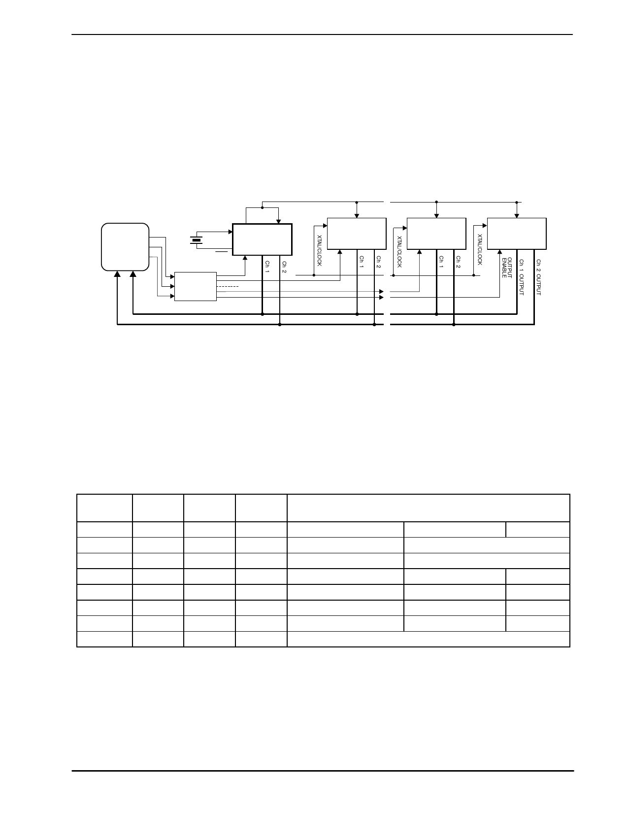
4.1 Xtal/Clock Distribution
The MX641 requires a 3.579545MHz Xtal or clock pulse input. With the exception of the Xtal, all oscillator
components are incorporated on chip. If a Xtal input is employed the Clock Out pin should be directly linked
to the Clock In pin.
To reduce component and layout complexity, the clock requirements of up to 3 additional MX641 microcircuits
may be supplied from a Xtal-driven MX641 acting as the system master clock. With reference to Figure 3, the
clock should be distributed as illustrated and the Xtal/Clock pins of the driven microcircuits should be
connected directly to VDD.
Note (see section 6.1.3) that the maximum load on the master Clock Out pin should not be exceeded.
µController
I/O Ports
Ch 2
Ch 1
CLOCK
OUT
CLOCK
IN
XTAL/CLOCK
X1
XTAL
MX641
(used as
Master
Oscillator)
VDD
3 to'N' LINE
DECODER
CLOCK
IN
MX641
CLOCK
IN
MX641
CLOCK
IN
MX641
"OUTPUT ENABLE"
ADDRESSING
Figure 3: Xtal/Clock Distribution and Output Multiplexing
4.2 Channel Outputs
Channel 1 and Channel 2 outputs operate together under the control of the Output Enable and Output Select
inputs.
Table 3 describes the operations.
The digital output is pin-selectable to one of three modes:
(1) Tone Follower mode: a logic level for the period of a correct decode.
(2) Packet mode: respond/de-respond after a cumulative period of tone or notone in a fixed (intrinsic
hardwired period that is not user controlled) period.
(3) High-impedance output: for device multiplexing.
System
Select
Preset
Level
X
0
X
0
0
1
1
1
0
1
1
1
X
X
X = don’t care
Output
Select
0
1
0
0
1
1
X
Output
Enable
0
0
0
0
0
0
1
Operating Mode
Mode
Sensitivity
Frequency
Packet Mode Output; Serial Data Control (see note)
Tone Follower Output; Serial Data Control (see note)
Packet Mode Output; Fixed Sensitivity
16kHz
Packet Mode Output; Fixed Sensitivity
12kHz
Tone Follower Output; Fixed Sensitivity
16kHz
Tone Follower Output; Fixed Sensitivity
12kHz
Tristate Output (High Z)
Note: Device sensitivity and system frequency must be serially loaded
Table 3: Operating Mode Configuration
ã2001 MX-COM, Inc.
www.mxcom.com tel: 800 638 5577 336 744 5050 fax: 336 744 5054
Doc. # 20480115.004
4800 Bethania Station Road, Winston-Salem, NC 27105-1201 USA All trademarks and service marks are held by their respective companies.
Share Link: 