M74HCT258M1R(1993) Просмотр технического описания (PDF) - STMicroelectronics
Номер в каталоге
Компоненты Описание
Список матч
M74HCT258M1R
(Rev.:1993)
(Rev.:1993)
STMicroelectronics

M74HCT258M1R Datasheet PDF : 12 Pages
| |||
M54/M74HCT257/258
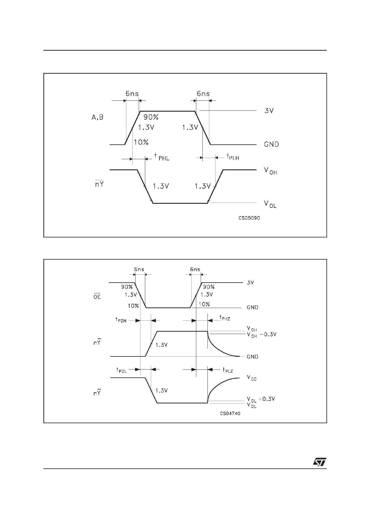
AC ELECTRICAL CHARACTERISTICS (CL = 50 pF, Input tr = tf = 6 ns)
Symbol
Parameter
Test Conditions
VCC
(V)
tTLH Output Transition 4.5
tTHL Time
tPLH Propagation
4.5
tPHL Delay Time
(A, B - Y)
HCT257
HCT258
TA = 25 oC
54HC and 74HC
Value
-40 to 85 oC -55 to 125 oC Unit
74HC
54HC
Min. Typ. Max. Min. Max. Min. Max.
7
12
15
18
ns
19 30
38
45
ns
17 27
34
41
tPLH Propagation
4.5
tPHL Delay Time
(SELECT - Y)
20 30
38
45
ns
tPZL Output Enable
tPZH Time
4.5
RL = 1 KΩ
18 30
38
45
ns
tPLZ Output Disable
4.5
RL = 1 KΩ
tPHZ Time
16 30
38
45
ns
CIN Input Capacitance
5
10
10
10 pF
COUT Output
10
Capacitance
pF
CPD (*) Power Dissipation
HCT257
34
Capacitance
HCT258
33
pF
(*) CPD is defined as the value of the IC’s internal equivalent capacitance which is calculated from the operating current consumption without load.
(Refer to Test Circuit). Average operting current can be obtained by the following equation. ICC(opr) = CPD •VCC •fIN + ICC/4 (per Channel)
6/12
Share Link: